
Fire safety is a critical concern in the design and construction of buildings, influencing both the selection of materials and the engineering of structural and functional elements. Among the many strategies for mitigating fire risks, implementing rigorous fire test standards is paramount. These standards serve as benchmarks to evaluate the fire resistance of building components, ensuring that they can withstand fire for a designated period, thereby allowing safe evacuation and minimising structural damage.
However, the landscape of fire test standards is far from uniform. Different countries and regions have developed their own methodologies and criteria for assessing fire resistance, reflecting variations in building practices, regulatory environments, and fire safety philosophies. These differences can have significant implications for global trade, construction practices, and safety regulations.
This article aims to explore the differences in fire resistance test standards across various jurisdictions. By examining the methodologies, criteria, and outcomes associated with these standards. We have compared ASTM E119 to ISO834-1 in this article. UL standards and ASTM standards have almost the same resistance to fire test curves and instrumentation. ISO 834-1 has the same instrumentation as per IS/ISO 834-1 and EN 1363-1 standards. BS 476-20 and AS 1530-4 standards have the same curve but different instruments.
Differences In The Time Temperature Curve:
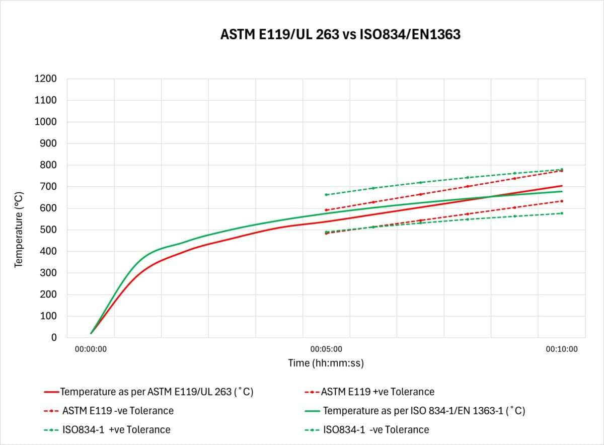
When planning for fire resistance testing using a cellulosic curve, it is important to note that the cellulosic curves in American standards differ from those in other international standards. In the ASTM E119 and UL standards, the cellulosic curve is not expressed as a formula; instead, it is presented in a tabular format with the temperature setpoints at 5-minute intervals. This allowed testing laboratories more flexibility in manually adjusting the temperature of the furnace. However, with the emergence of modern control systems, it is possible to accurately control the furnace temperature every second.
Standards like BS 476-20, EN 1363-1, ISO/IS 834-1, and AS1530-4 provide the time-temperature curve using an equation: T=345 log10(8t+1)+20, where, T is the furnace temperature at the time t in °C, and t is time into the test, measured from the ignition of the furnace, in minutes. Because this curve is equation-based, it can generate data every second, enabling precise furnace control.
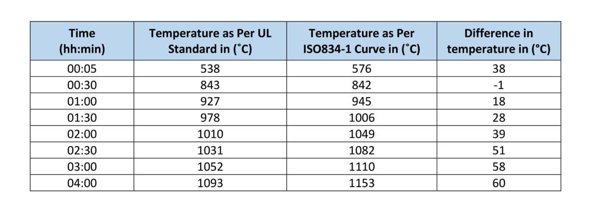
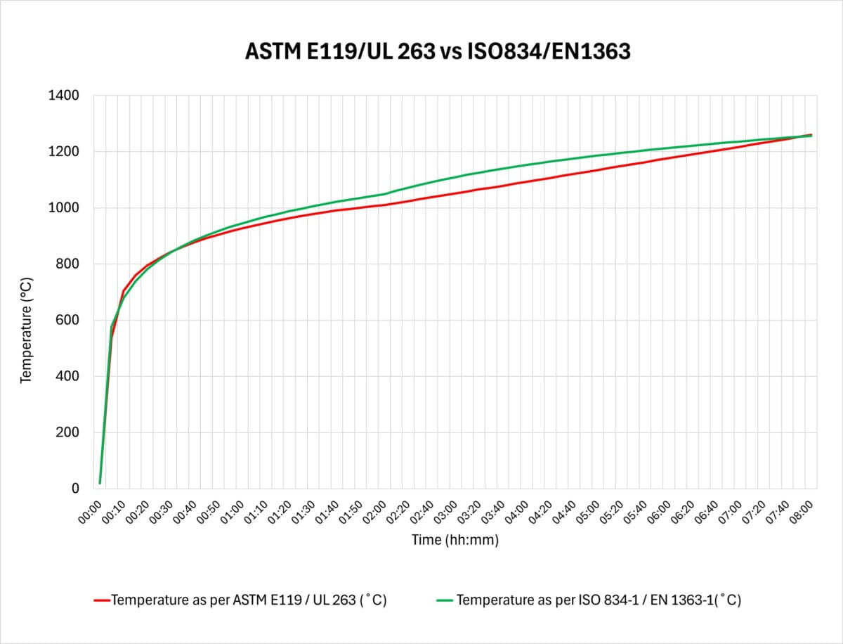
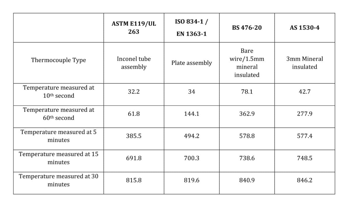
Upon analysing the time-temperature data, noticeable temperature variations between American standards and other international standards are evident. These differences are outlined in Table 1 and illustrated in the accompanying graph below.
Difference In Instrumentation:
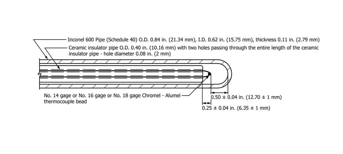
When comparing ASTM E119, BS476-20, EN 1363-1, IS/ISO-834 part 1, and AS1530-4 test standards, differences in instrumentation become apparent, particularly in the method of temperature measurement using K-type thermocouples. Each standard employs different practices for positioning the thermocouple junction in relation to the heat source. This variation in thermocouple assembly not only affects how the furnace is controlled but also significantly impacts the specimen’s exposure to heat, despite using the same time-temperature curve. This is due to the varying time constants of the different thermocouple assemblies. Refer to Figures 1, 2, and 3.
UL/ASTME119:
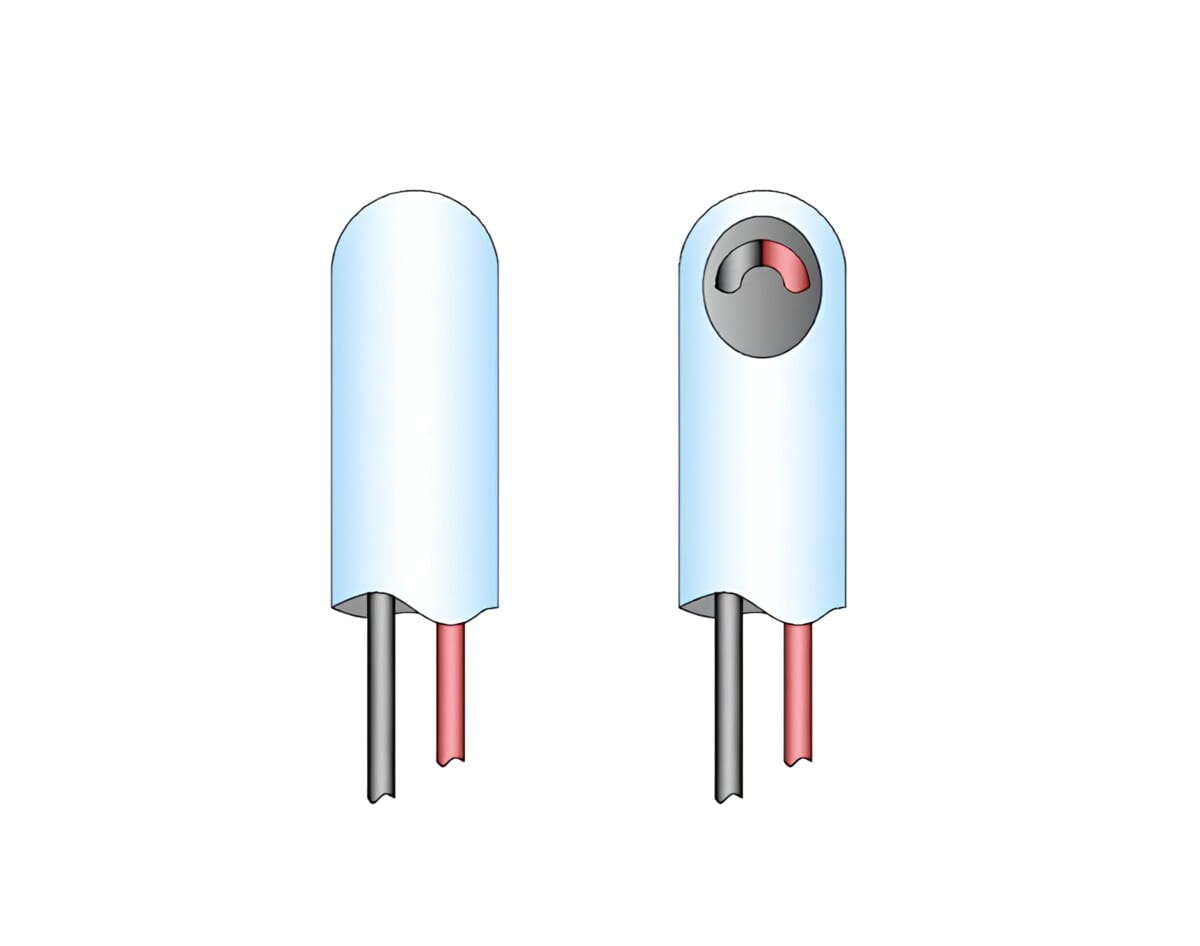
In ASTM E119/UL263 and other UL standards, K-type thermocouples with 16-to-18-gauge wire are enclosed within an Inconel tube. Temperature measurement involves the heat passing through a 2.79mm thick layer of steel alloy and an air gap, before reaching the measuring tip of the thermocouple. This setup results in a slower response time for the thermocouple, potentially increasing the sample’s exposure to heat. The time constant of this assembly typically ranges between 300 to 400 seconds. However, once equilibrium is achieved, this sensitivity may become less significant. Refer to Figure 1
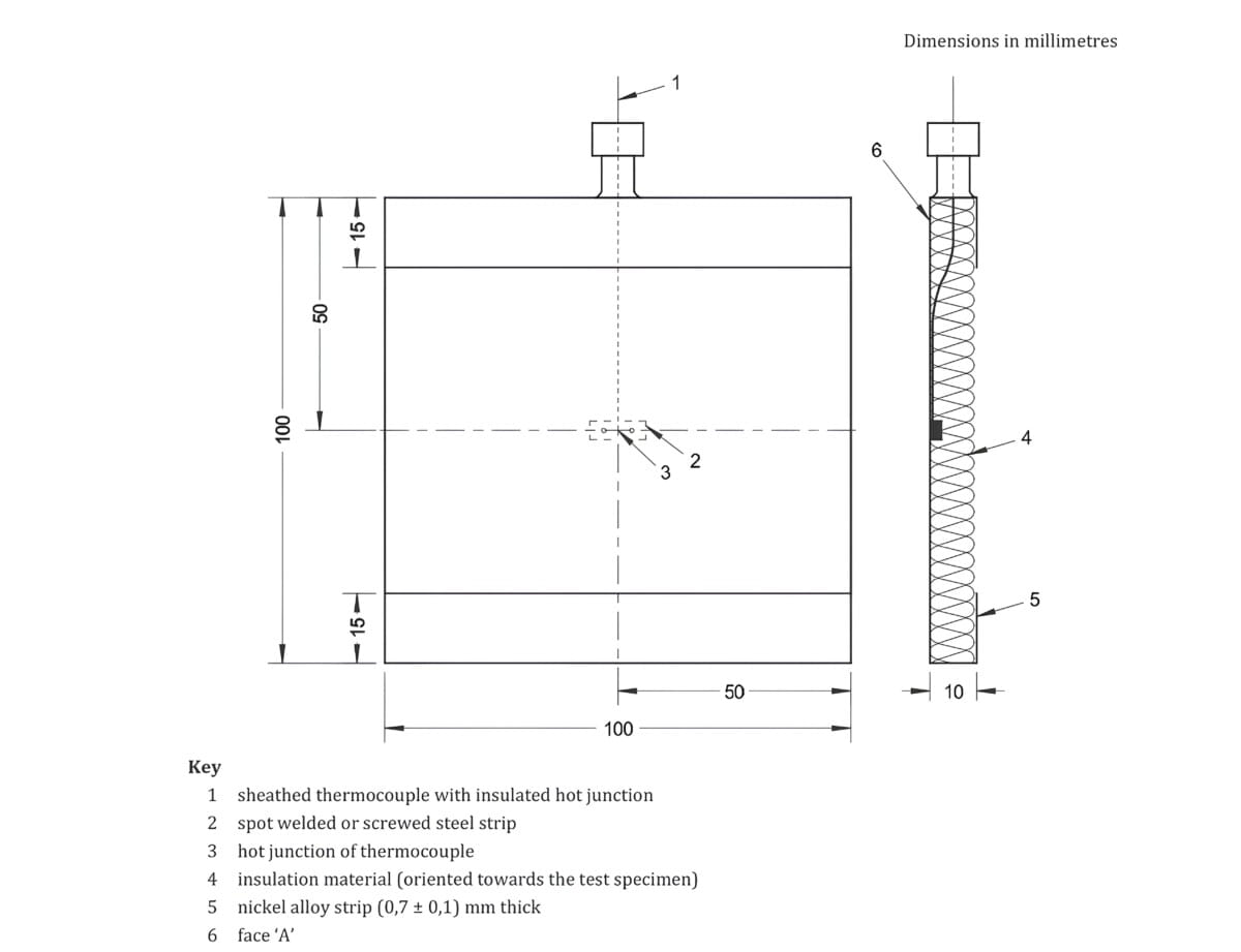
ISO834-1:
The plate thermocouple assembly used in EN 1363-1 and ISO 834-1 consists of a mineral-insulated K-type thermocouple with a nominal diameter of 1.5 to 2mm, securely fixed to a 0.7 mm-thick Inconel plate. To prevent direct exposure, an insulation pad shields the thermocouple from the specimen side. This design ensures that the temperature must first pass through the conductive Inconel sheet before reaching the sensing end of the thermocouple. The assembly is engineered to achieve a more uniform temperature reading, minimising fluctuations during the test.
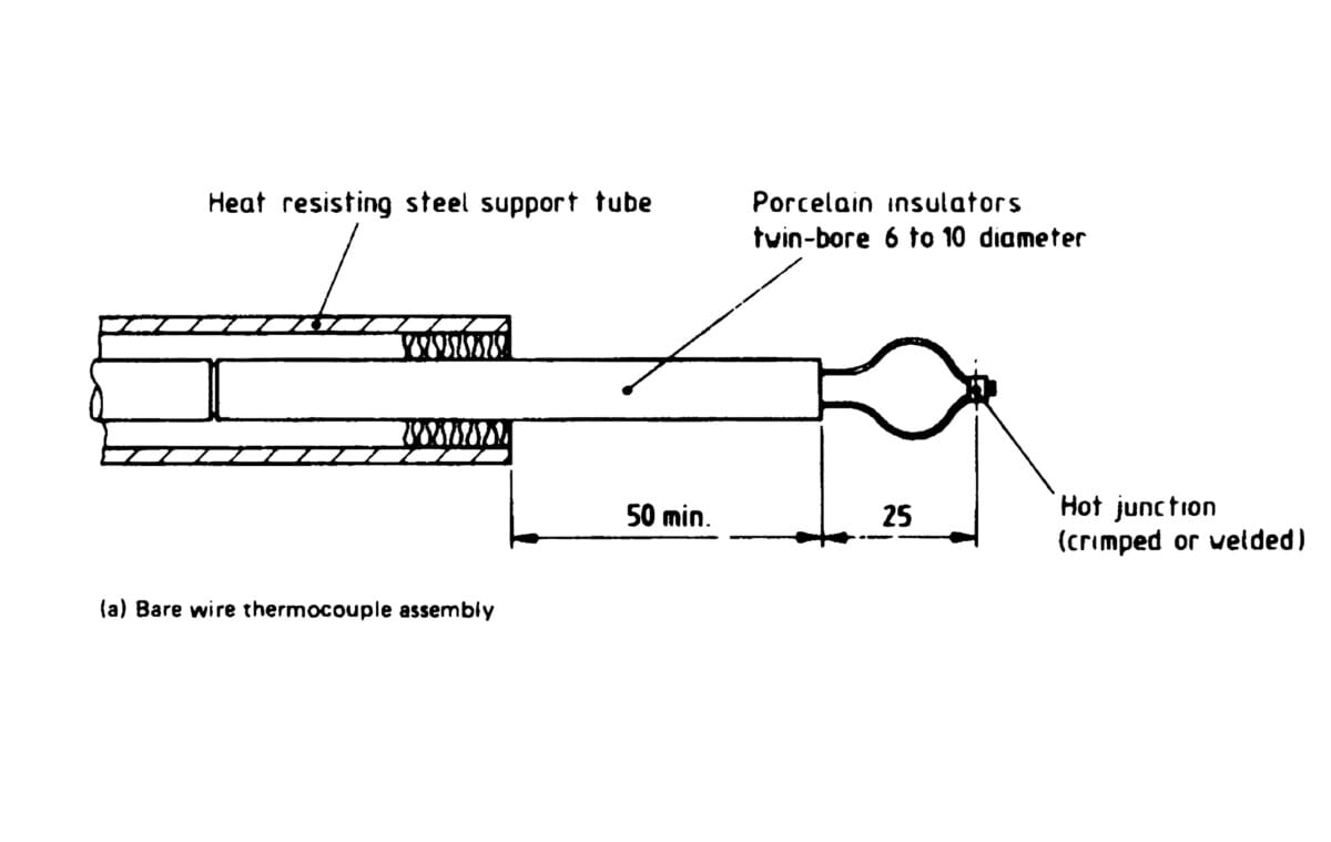
BS476-20:
In BS 476-20, either 0.75mm to 1.50mm bare wire K-type thermocouples or 1.5mm mineral-insulated K-type thermocouples are employed to control the furnace. These thermocouples exhibit the lowest time constants and therefore offer the quickest response times compared to other standards. This rapid response allows the furnace to be controlled more swiftly than with other thermocouple assemblies.
This quick response also results in reduced heat exposure on the specimen.
AS1530-4:
Mineral-insulated K-type thermocouples with a nominal diameter of 3mm are utilised for furnace temperature control in this standard. These thermocouples boast a response time comparable to those specified in BS 476- 20.
Experimental Results On The Comparison Of Heat Exposure Using Different Thermocouples For Resistance To Fire Tests.
We conducted an experiment to assess temperature variations across different thermocouple assemblies during a fire resistance test.
For The Study, We Selected The Following Thermocouple Assemblies:
- ASTM E119/UL 263 thermocouple assembly
- BS 476-20 thermocouple assembly
- ISO 834-1 thermocouple assembly (same as in EN 1363-1)
- AS 1530-4 thermocouple assembly
The furnace was operated using the BS 476-20 thermocouple assembly, known for its rapid response, while temperatures recorded by the other thermocouples were compared simultaneously. Data was logged at 1-second intervals throughout the experiment.
The furnace followed the ISO 834-1 curve (T=345 log10(8t+1) +20, where T represents temperature and t denotes time in minutes).
Results Of The Experiment:
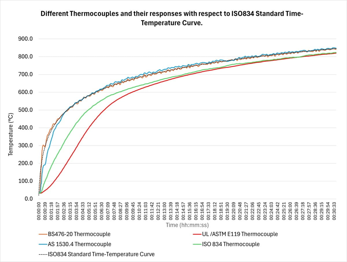
A significant temperature difference of up to 300°C was observed during the initial minutes of the test. This difference narrowed as the thermocouples became saturated. Refer to Graph 3 for details. The measured temperatures are also listed in Table 2.
Thermocouples with slower response times produced a smoother curve, as they did not capture the fluctuations in the gas temperature inside the test furnace. In contrast, fast-response thermocouples recorded the exact temperature fluctuations every second, allowing for precise control of the test furnace.
Inference:
If the furnace is controlled by ASTM E119/UL 263 thermocouples, the actual temperature the specimen gets exposed to in the initial minutes of the test will be much higher than that of BS 476-20. This is to be coupled with the fact that there is a difference in the time-temperature curve, too.
Similarly, specimens are exposed to higher temperatures when tested according to ISO 834/EN 1363-1. This is why a test conducted under one standard cannot be considered exactly equivalent to another, even if the time-temperature curves appear the same. The experiment also highlights why instrumentation used for one standard should not be used for another.
Furnace Pressure Conditions And Pressure Probes
One of the primary requirements for any test furnace is the ability to maintain a neutral pressure plane inside the furnace at the specified height according to the standard. However, there are some key differences between the test standards.
For tests following the general requirements of ISO 834-1 and EN 1363-1, unless otherwise specified, for all vertical elements, a zero-pressure plane is maintained 500mm above the notional floor level. The height of the zero-pressure plane must be adjusted to ensure that the pressure at the top of the specimen does not exceed 20Pa.
For horizontal elements, according to ISO 834-1, a 20Pa pressure plane is to be established 100mm below the underside of the specimen or the notional ceiling level. In EN 1363-1, the pressure plane for horizontal elements is established relative to the notional floor level, ensuring that the pressure on the underside of the test specimen does not exceed 20Pa.
Additionally, when assessing furnace pressure conditions, ISO 834-1 assumes a pressure gradient of 8 Pa per meter, whereas EN 1363-1 assumes a gradient of 8.5 Pa per meter height of the furnace.
Even though the difference in measured values may be insignificant, the probes used for pressure measurements vary across different standards. For instance, the tube-type probe used in ISO 834-1 has 3mm holes, while the same probe in EN 1363-1 has 1.2mm holes. Similarly, UL 10C specifies a probe similar to ISO 834-1, whereas UL 263 uses a different probe with 1.5mm holes.
Cotton Pad
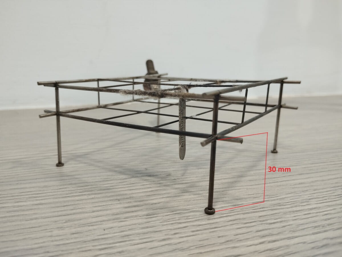
The cotton pad test determines the specimen’s integrity during a fire resistance test. Although the cotton pad test procedure appears to be similar in various standards, there are some key differences in the equipment and the time of application.
For tests as per EN and ISO standards, the cotton pad holder is designed in such a way that the cotton pad is 30mm away from the surface of the specimen. In contrast, for ASTM and UL standards, the cotton pad is 25mm away from the sample.
Regarding the time of application, most standards specify a maximum of 30 seconds or until ignition, while BS 476-20 limits the time of application to 15 seconds.
Guidelines On The Application Of Cotton Pad:
According to BS 476-20, the cotton pad should no longer be used if the temperature on the unexposed side near the gap reaches 300°C, as measured by a roving thermocouple. ISO 834-1 includes a comparable provision.
UL 10C specifies that cotton pads shouldn’t be used on door assemblies where the average temperature exceeds 250°C (450°F) above ambient temperature. Additionally, single-layer metal doors are exempt from the cotton pad test requirements.
Gap Gauges
Most of the fire resistance test standards specify a 6 mm and 25 mm gap gauge for the evaluation of the integrity of the separating elements. Usually, an Integrity failure is deemed to occur when the specimen allows penetration of a 25 mm gap gauge or when the gap developed in a specimen is large enough for a 6mm gauge to travel a length of 150mm.
However, certain standards like EN 1364-2 – Fire resistance test on non-load bearing ceilings exempt the use of gap gauges, considering the safety of the laboratory personnel and instead, a visual assessment of the gaps is prescribed.
Hose Stream Tests
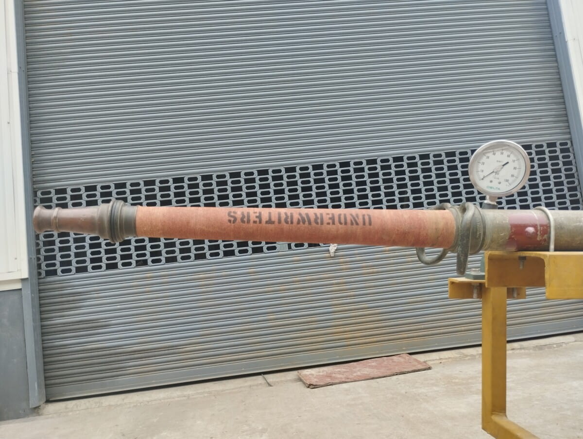
The hose stream test, conducted immediately after the fire test, is a crucial requirement in ASTM and UL standards for most separating elements. If a specific standard lacks a procedure for this test, ASTM E2226 guidelines are followed.
The test employs a UL standard playpipe equipped with a 29mm discharge tip to deliver water. Water pressure at the playpipe’s base is set at 30 psi for tests lasting less than 3 hours and 45 psi for tests lasting 3 hours or longer.
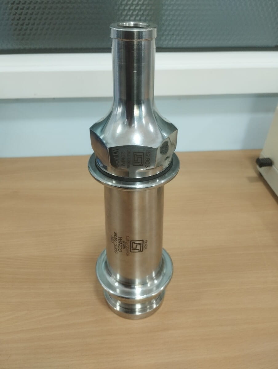
The Indian standard for through penetration fire stops, IS 12458, specifies a hose stream test at similar pressure but with an IS903 nozzle instead of a UL playpipe.
In contrast to ASTM and UL standards, EN and ISO standards for fire resistance tests do not include hose stream tests as part of their compliance criteria.
Conclusion:
The diversity in fire resistance testing standards poses challenges for international building practices, particularly in regions like India, where multiple standards may apply. For instance, a material deemed fire-resistant under one standard may not necessarily meet the criteria of another, complicating cross-border construction projects and the global trade of building materials. Understanding the differences in fire resistance testing across various standards is crucial for architects, engineers, and regulators to design and construct truly fire-safe buildings. By acknowledging these differences and working towards harmonisation, the global construction industry can improve fire safety standards, ensuring better protection for people and property worldwide.