
Façade acts as the boundary between the external and internal environments of a building. As it is the occupants’ interface with the surrounding environment, it has a large impact on energy efficiency and indoor quality performance of a building. For a Platinum-rated building (under IGBC New Buildings Rating System version 3.0), the solar gain through façade accounts for 25 per cent of the building cooling load. For a building which complies with the specifications of ASHRAE Standard 90.1-2010 (to fulfil Energy Efficiency Mandatory Requirement 2, under IGBC New Buildings Rating System version 3.0), the solar gain through façade accounts for 35 per cent of the building cooling load. For a conventional building, the percentage increases to 50 per cent. A well designed façade with appropriate material specifications can reduce the solar gain by 50 per cent, and exploit daylight to reduce the peak lighting load by 60 per cent. This article highlights the drawbacks of the conventional way of designing façade and proposes a parametric framework (with the help of a case study) of developing and comparing façade design concepts and/or options for its global optimization.
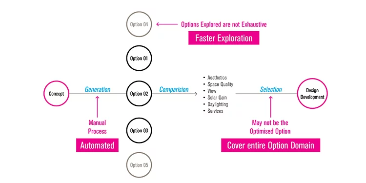
Conventionally, concepts and/or options are modelled suomoto, and environmental analysis tools are used for validation in the later stages of design. Architects design parallel facade concepts at the concept design stage. Concept in this context means a design system using which different options can be generated – for example, horizontal fins or vertical fins or a combination of horizontal and vertical fins. Upon consultation with the client, one of the concepts is selected to be developed further (as shown in Fig. 1).
The process of further development, typically involves manual modelling of 3-5 options based on the selected concept. Options in this context mean variations of the same design system- for example, for a design system of vertical fins, two options can be, 300mm deep fins at a distance of 750mm c/c, and 600mm deep fins at a distance of 1200mm c/c. One of these options is selected with the client, which is developed in detail at the design development stage. Sustainability or Façade consultants are usually hired at the Design Development stage, whose input remain absent at the Concept Design stage where most of the key design decisions are taken. The drawbacks of the conventional workflow are as following:
- The initial design concepts are not compared quantitatively.
- Each initial design concept is not judged to its full potential, because the options of each design concept are modelled manually.
- Consequently, the options modelled are not exhaustive.
- Because the options modelled are not exhaustive, the final selected option is the local optimised option.
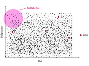
If the options are plotted on a Cost vs Performance graph (as shown in Fig 2), they are noted to be randomly distributed. These options which are usually designed using thumb rules, and compared within themselves ought to lie inside the shaded circle in the graph. In the example of a design system of vertical fins, among the two, the option with 600mm deep fins will be better for daylight; but the global optimum might lie between 300-600mm depth and 750-1200mm c/c distance. Even for such a simple system, finding the best combination of depth and c/c distance is impossible without generating and simulating all the possible combinations. Such an exploration is not feasible when performed manually because of the time required to do so. Consequently, there is a need of a system and a workflow which take care of the following:
- Establishing a common quantitative quotient to compare parallel design concepts and/or options.
- Each design concept and/or option needs to be exhaustively explored to generate different possibilities and achieve full creative potential.
- The exploration needs to be automated to save time.
- With a common quantitative quotient, the auto-generated and exhaustive options can be optimised globally.
Parametric Workflow
These requirements are met by the use of computation which exploits the speed, memory and calculative power of computer and applies them strategically in the design process.
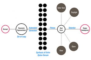
The parametric workflow has three key parts (as shown in Fig. 3) described as following:
- Parametric Representation: the parameters (numbers) chosen to represent the facade for optimisation. Every geometrical dimension of the facade and material specifications are kept flexible within permissible domains to generate the options.
- Optimisation Algorithm: the form-generating rule(s) that coverts and assigns the parameters into geometry and material specifications, and connects the parent software to an environment analysis tool. This process is set on loop by varying the parameters to automate exhaustive exploration. When the looping is concluded, the result is sorted according to their performance indices (or fitness) to filter out the best performing options.
- Simulation: for each run of the loop in the algorithm, the option generated in the current loop is automatically exported to an environment analysis tool to use its existing simulation engine. The result based on one or more modules of optimisation (solar gain, daylight, glare, view etc) is imported back into the parent software and stored against the option number. This concludes one loop.
In the example of a design system of vertical fins, the depth and c/c distance are the two parameters. Assuming the domains to be 300-600mm and 750-1200mm respectively, and discretized at an interval of 10mm, every possible combination ((300, 750), (300, 1200), (600, 750), (600, 1200), (450, 900), (550, 930) etc) of the two parameters are generated and simulated for daylight. For every 1462 combinations, the result is stored in an array which is sorted to give the best performing options.
Using computation for design exploration and optimisation has always been a niche service since the development of Sketchpad by Ivan Sutherland in 1963. Since architects are not formally trained in computation, such methods were used by an exclusive group who could develop custom codes in either 3D modelling software (for eg, AutoLISP in AutoCAD) or generate 3D images and models in traditional coding languages (for eg, Processing built on Java). The challenge lied in bridging the gap between 3D modelling and coding, and using it for performance calculations or simulations. But recent development of sophisticated computational design tools has simplified the integration of computation in the design process. Visual programming languages like Grasshopper (which runs on 3D modelling software Rhino) and Dynamo (which runs on Building Information Modelling software Revit) have made it easy for architects to undertake the task of coding. These new languages are connected with environment analysis tools like Ecotect, eQuest and EnergyPlus, which makes the automaton of iteration and simultaneous simulation simpler.
Parametric Representation
Parameters are can be divided into the following two types:
- Intrinsic parameters- a number which represents a property of the façade which does not change with quantity, eg, visible light transmittance of glass, u-factor of aluminium etc.
- Extrinsic parameters- a number which represents a dimension or value of the façade which changes with quantity, eg, depth of fin, quantity of glass etc.
Both kinds of parameters can be variable or constant. In the example of a design system of vertical fins which is optimised for daylight, the depth and c/c distance are extrinsic and variable parameters. The other kinds of parameters which can constitute a complete parametric representation for this example are as following:
- Extrinsic and constant parameters- width of fin, sill and lintel level of fenestration, length and height of facade.
- Intrinsic and constant parameters- reflectance of fin, visible light transmittance of glass, reflectance of walls, ceiling and floor.
Ideally, all the above mentioned parameters excluding width of fin, and length and height of façade should be taken as variables for optimization. However, in most cases due to aesthetic preference or budget constraints, some or most of the parameters are kept constant. The selection of parameters to represent the design, the variable or constant nature of every parameter, the domain of every parameter and the discretization of every domain become the most important decisions in the process. These decisions consequently affect the range of options that are generated. As a common measure, only extrinsic parameters are taken as variables with high discretization of domains when comparing parallel concepts, to understand the mutual differences. When exploring the global optimum within a design concept, as many parameters as possible are taken as variables with low discretization of domains.
The technique of parametric representation opens new ways of interpreting geometries. It marks a paradigm shift where relationships between elements are used to manipulate and inform the design of geometries and structures. The focus shifts from the process of modelling geometry, to the process of defining geometry. The designer’s attitude thus transforms from developing a pre-conceived idea of a form and directs towards the form-generating rules and the dependencies between the parts.
Case study- Façade of a Hotel
Objective: To optimise the façade for minimum solar gain and optimised daylight
Note that, optimized daylight is calculated using daylight factor. IGBC New Buildings Rating System version 3.0 prescribes that the percentage of regularly occupied spaces in the building, which achieves daylight illuminance levels within the range 110-1100 lux in a clear sky condition on 21st September at 12 noon, at working plane should be higher than 75 per cent. This is analogous to a daylight factor of 2.
The following strategy is adopted to optimize the façade: (Fig.4)
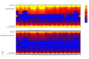
- For a glass of vlt 0.50, the daylight factor is 4.9. On interpolating the daylight factors with various vlt specifications, it is determined that for a vlt of 0.21, the daylight factor becomes 2.
- The solar gain for vlt 0.21 (existing design) is taken as 100 for comparison with optimized options. It is to be noted that the solar gain for vlt 0.50 (existing design) is 238.
- The designed hybrid fin is to aid the selection of a higher vlt (for a clearer view) without increasing or reducing the daylight factor, and reduce solar gain at the same time.
- The hybrid fins are optimised with the material properties of solid aluminium and tensile fabric.
Fact file
Location: Ahmedabad
Hotel Type: Business
Built up Area: 7580 sq m
Total Façade Area: 3675 sq m
Parametric Representation
The solar shading coefficient studies show that horizontal shade is required for the summer months and vertical shade is required for the winter months. A combination of the two make the facade look like a series of grillage (as shown in Fig. 5).So, instead of a direct super-imposition of the horizontal and vertical shades, a hybrid fin is conceptualised which is derived by interpolating the intersections of the shades and the mid-points of the vertical shades. The configurations are shown below. The hybrid fin has a contemporary expression, which animates the facade and makes it dynamic.
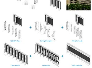
Following are the parameters used for parametric representation:
- Intrinsic and Variable-u-factor, shading coefficient, and vlt of glass.
- Intrinsic and Constant- u-factor, shading coefficient, and vlt of the fins.
- Extrinsic and Variable- fin type, starting orientation, length, mutually clear distance, and total rotation of hybrid fins; sill and lintel level.
- Extrinsic and Constant- façade length and height.
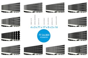
These parameters yield 77,24,800 possible combinations (Fig. 6). Manually modelling and simulating these many combinations is practically impossible. Parametric representation aids the conversion of the concept of hybrid fins (genotype) into different variations (phenotype) based on the domain and discretization.
Optimisation
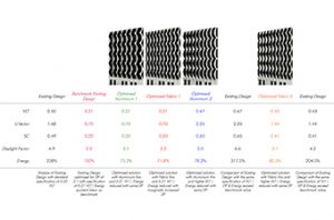
The summary of result of optimization is shown in Fig. 7. The following highlights the method for reading the same (from left to right):
- Existing design- Analysis of existing design with standard specification of 0.50 vlt.
- Benchmark Existing Design- Existing Design optimised for daylight factor, specification of vly comes out to be 0.21 vlt. Energy quotient taken as benchmark.
- Optimised Aluminium 1: Optimised solution with aluminium fins and same vlt as benchmark existing design. Energy reduced with same daylight factor.
- Optimised Aluminium 2: Optimised solution with aluminium fins and higher vlt. Energy reduced with same daylight factor.
- Existing Design: Comparison of existing design with the same vlt specification of optimized aluminium 2. Daylight factor & energy exceed benchmark value.
- Optimised Fabric 2: Optimised solution with fabric fins and higher vlt. Energy reduced with same daylight factor.
- Existing Design: Comparison of existing design with the same vlt specification of optimized fabric 2. Daylight factor & energy exceed benchmark value.
Genetic algorithm is used to find the optimised fin for the facade. The algorithm generates and iterates through generations of solutions called candidate solutions. Each generation consists of a fixed number (say 50) of solutions. Parameters are randomly generated for the first generation of the algorithm. Then, each of those solutions is evaluated against solar gain and daylight factor. The best solutions (say top 50 per cent, i.e. 25) are then selected and taken to the next generation by default. The rest of the candidates (remaining 25) of the next generation are populated by mutually combining the parameters of the best solutions of the previous generation (say 10), by mutating some of the parameters of the best solutions of the previous generation (say 10), and by introducing new candidate (say 5) solutions by generating all the parameters randomly. This process is iterated until a benchmark is reached or a pre-defined number of iterations are computed (in this case, 1000). Genetic algorithm uses techniques inspired by natural evolution, such as selection, crossover and mutation. The solutions of the last generation (marked as optimized solution in Fig. 8) converge around daylight factor of 2. The highlighted solutions are marked in the solar gain vs daylight factor graph. Optimised solutions with solar gain less than 70 per cent have vlt lesser than 0.21 (existing benchmark).