
How BIM has influenced building and façade design?
BIM is a massively disruptive force that is transforming every aspect of the construction industry. But it is not Building Information Modelling (BIM) per say, but rather digital engineering and delivery and the way we approach efficient information management on a project that is changing.
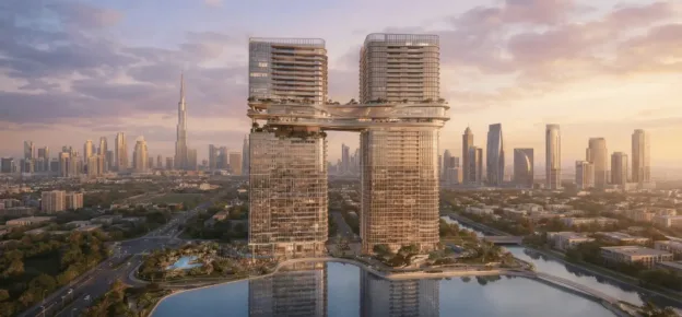
This current revolution is long overdue as many traditional design and construction approaches have not changed in hundreds of years. What has changed is the adoption, workflows, and processes created to fully utilize 3D technologies, which have allowed the design team especially architects, to imagine and create more complex forms than ever before.
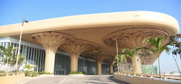
The façade as the outer face or skin of any building is what is most visible to the outside world and often a building is better known for its striking façade more than anything else. In addition, the look, feel and geometry of the façade often drive the entire concept for the building’s interior spaces.
Very fortunately in my 35-year career where the last 10 plus years have been in the Middle East, I have had the opportunity to work on many projects with exceptionally complex and iconic façades that have challenged every aspect of digital engineering design and construction.
How Building Information Modelling (BIM) and parametric are implemented procedures in the design process?
It is important that architects and the design team generally can convey their vision or design intent to all necessary project stakeholders. Traditionally, this would have been done using presentations or sketches, or references to real-world items or natural elements.
But in this new digital world, this is best achieved using a variety of geometric and parametric modelling tools which allow the creation of a digital representation of the physical and functional building shape, form, or surface that will define the façade.
This streamlines the process of design and communicates complicated information accurately to everyone involved, allowing the joint work of architects, clients, builders, engineers, etc. to occur within a single intelligent and shared process, making it a critical workflow to increase efficiency and cross-discipline integration.
While inherently parametric, the common approach of utilizing BIM is mainly through labour-intensive modelling. The usability of BIM throughout the design process is strengthened, by improving the integration of parametric-driven parameters which automate the modelling workflow reducing time and therefore cost.
Efficient reuse of data or information in various forms across all disciplines is at the heart of what digital engineering is all about, not so much “Building Information Modelling” but rather “Better Information Management”, ensuring efficient reuse of project data.
What are the requirements and differences between BIM and Parametric procedures?
Here it is best to consider we have two separate approaches or two differing communities. The difference between these approaches is emphasized when focusing on the semantic meaning of created objects.
Parametric design is almost exclusively oriented towards creating geometry. While this geometry is more and more tied to external analysis tools, to evaluate different performance criteria such as day-light availability or energy consumption, the process is inherently focusing on modelling. As such, the resulting geometry contains little information and is not so different from geometry created in traditional CAD systems: points, curves, and surfaces placed on layers.
Fueled by the requirement for iterations, pioneering, and prototyping, parametric design has allowed engineers and designers to rethink their approach in numerous ways and introduce new and daring approaches that might otherwise have been dismissed.
At the other side of the specter, BIM relies on a pre-defined semantic structure. All entities have a clear meaning and function. The culmination of the BIM structure is the Industry Foundation Classes (IFC), which describe all possible and foreseeable building elements in over 800 entities, 350 property sets, and over 100 data types.
Whether the structural steel members of a façade or curved roof or the setting out of a ceiling with lighting fixtures or fire detection items, each relies on the rules and definitions of the products being used and the structured profile that they follow.
What are the latest advancements and trends?
Personally, I find it almost impossible to keep up with the technological change in current times, what I will say is that developments that allow complex calculations or data manipulation to be achieved through a more user-friendly interface are number one in my book.
I am of course referring to the visual programming environments that have taken over many of our design processes in recent years. These are easy to learn as they provide many built-in objects that are organized in a flowchart-type nature.
Basically, a typical text-based programming language means the programmer must think like a computer, while a visual programming language lets the programmer describe the process in terms that make sense to humans. This form of coding has opened a world of possibilities not just in terms of simplicity of use but also in terms of building complex operations by combining pre-structured modules, many of which are now available as they are being shared freely online.
How to bridge the gaps between parametric design and BIM?
“Parametricism” is a term being used for a new global style of design that covers all industries and disciplines and implies that all elements are parametrically malleable with the right computational design tools and manufacturing methods.
Basically, any item can be transformed from its initial state, through a computational process bound by constraints and into a future state. These skills however do not come naturally and therefore traditional roles and responsibilities are changing. Whether through education, upskilling, or development, new roles are now emerging for computational experts, parametric modelers, data analysts, visual programmers, data miners, and the like.

However, don’t for a minute think this wave is affecting the whole industry. In my experience many organizations, especially in the Middle East, are still struggling to come to terms with the basic concept of 3D BIM, never mind digital or computational engineering.
So, what you are left with is a huge gap, growing by the day, between the international tier 1 organizations that are actively adopting parametric thinking and pushing the industry capability forward and the smaller tier 2 or 3 organizations further down the food chain who are trying desperately to continue for as long as possible in 2D CAD, just like they have always done.
While parametric design can process thousands of iterations in minutes, removing tedious trudge work to find the optimum solution, it is still a human decision that ultimately will make the final choice.
What are the limitations of BIM/parametric design?
Arguably the only limitation is your imagination. However, there is a very steep learning curve involved (like any other skill) parametric design requires hundreds of hours of practice, patience, and perseverance. While the traditional style of designing usually focuses on the 2D plan first, the parametric design focuses on extensive data collection & validation and the setting up of relationships between parameters. Plus, all this needs to be set up at the beginning of the project. Additionally, since this method of design heavily relies on the data we provide during the design phase, extensive research and data collection are usually done first. Anything and everything, from site location to available materials, will contribute key data to the process.
Unfortunately, parametric design is not always the one to steal the show. It requires a large amount of time investment at the start, where various relationships and algorithms are defined. This does not sit well with some organizations with limited resources, on tight budgets or schedules.
If the end product is a production-ready model, then the idea is feasible, but for small companies, where the end product is only a 2D Drawing and a visualization of the finished product, the entire scheme might not work out cost-effectively. In this case, the traditional design might still be the best choice.
What are the benefits with respect to implementing BIM and parametric processes for façades?
The advantage of any computational process is of course the ease with which you can accommodate change. Once the initial formula or program is configured, usually with a set of baseline settings, then any further change is just a simple adjustment to the inputs and re-run.
Façades are often simple geometric shapes or patterns repeated to appear complex. Therefore, a parametric process using a geometric pattern can be generated with ease.
Combine this with the fact that most parametric design programming tools accommodate seamless integration with other traditional software such as environmental analysis, building physics, structural simulation, and clash test, and then this solves the need for multiple copies of the data on separate platforms as all the data is linked and interoperable.
The final step is that with every adjustment you make to your parametric design, the 3D model automatically creates the optimized solution and then updates the extracted drawings, BOQ, and schedules. Now you really have a solution that is to replace CAD with CODE.
Having worked with and for several consultants and façade manufacturers, I have experienced these processes firsthand. This has allowed me an insight into the complexities of façade systems and their installation both traditional and bespoke. However, it is wise to remember that the world of design inside a computer, where your 3D model can be measured to the millimetre, is far removed from a construction site where a build-up in structural steel fabrication tolerances can make a vast difference to the actual final position of the façade panels.
Why does BIM appear to be fundamental in the current architectural design? How can architects use BIM to streamline complex façade designs?
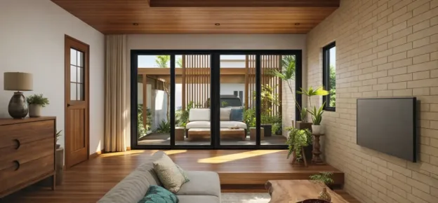
The use of BIM or parametric design is normally associated with complex shapes and curved geometry. However parametric definitions can be used for material and manufacturing optimization or simply to produce better and faster impressions or iterations when designing traditional rectangular glazing solutions.
Parametric design for façade is the application of computational strategies to the design process. While designers traditionally rely on experience and intuition to solve complex design problems, computational design aims to enhance that process by encoding design decisions using computer power and language. The result is a graphic representation of the steps required to achieve the end designs.
An external architectural façade is one of the most expressive, inspiring, and complex aspects of building design. It is the outermost skin with a multitude of roles from visual character to the weatherproof barrier. Today, the façade, interior skin, or cladding can be a complex as the building itself and balances the aesthetics, visual character, structural stability, solar gain, daylight, visibility, thermal comfort, and zoning together in one component.
How has BIM changed the façade modelling?
Any project with a BIM requirement means that design reviews focusing on fully coordinated 3D models now feature the façade like any other discipline.
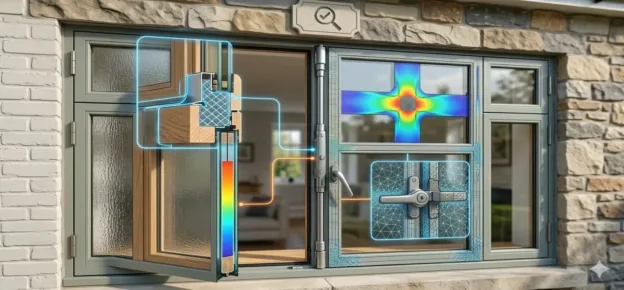
The total façade envelope can be around two meters in section. This is from outer skin, through weatherproof panelling and insulation to primary and secondary structural steel and then to interior mounting and final finish of the internal skin. This extensive zone in many cases also needs to accommodate MEP services. Therefore, creating a complex space that needs to be modelled, coordinated, and understood fully. Add to this mix a façade that may be curving in multiple geometric plains, and you can see that 3D modelling is not just a good idea, it is absolutely essential.
I have seen façades represented on a drawing as a single line because the external shape and form were considered all that was important. But once you fully understand the complex mounting and adjustment that must be anchored to the primary steel, you realize that “the devil is in the detail”, as they say.
As an industry, we now refer to the “Level of Detail (LOD)” of our 3D models. But in my opinion, the façade system has always been a difficult one to define. While I have explained why we should model a façade due to understanding the complexity, the reality of a fully modeled solution with every fixing, adjustment detail, and seal, would of course create a model that most normal users could not even open. Here a commonsense approach to what is modeled and what is not must be adopted.
How 3D parametric modelling and automation can help meet customer demands?
“The customer is always right”, or so the saying goes. Often the vision for the constructed asset originates from the client in some form or another, the challenge then for the architect is to realize that vision with a solution that meets the aesthetic, creative, and functional demands, while allowing the engineers to then create a design that can be manufactured and constructed.
The parametric process then allows for the accelerated crunching of design ideas and efficient options to find the optimum solution, therefore providing additional time to be spent on the artistic touch provided by the human expert input.
Fast and efficient optimization is a real game-changer. Whether reducing structural steel sizes used, or onsite fabrication time reduction, standardization of façade panel types and dimensions, or automatic development for space planning. Each utilizes a lot of data but is capable of substantial material and time savings.
Being able to then visualize these savings in a plain language format is critical. Several applications are now available to allow a client or customer to manipulate data in such a way so that they can themselves “play around with” the controlling parameters to adjust the solution as they see fit. This real-time interactive ability takes customer configuration to the next level.
How technology can be used to reduce costs, reduce defects, and improve designs?
Becoming efficient at any process by adopting whatever means possible, means that you can effectively complete that process in less time. Saving time in real terms means saving money, and that is the main driver behind almost everything.
The technology itself, whether software or otherwise is merely an enabler, it simply replaces the use of paper and pencil. Let’s remember, we humans can do whatever a computer does, it is just that they can usually do it faster and with fewer errors. The takeaway is, that we save time. With tried and tested effective processes and workflows in place, then deploying technology to do the work is usually a success.
The question of “improving design” in my opinion comes from what we have learned from our past experiences. The construction industry generally is not great at lessons learned or sharing valuable experiences for the benefit of everyone.
Being better at managing information intelligently provides the tools to allow us to make better-informed decisions and that knowledge then leads to better outcomes.
Some parametric processes can now even learn from previous iterations, therefore, understanding what is good and bad, and this then influences future solutions created.
In final summary smart solutions developed by the use of smart technology, in the hands of suitably smart people is a force to be reconned with and will shape the design and construction industry going forward.