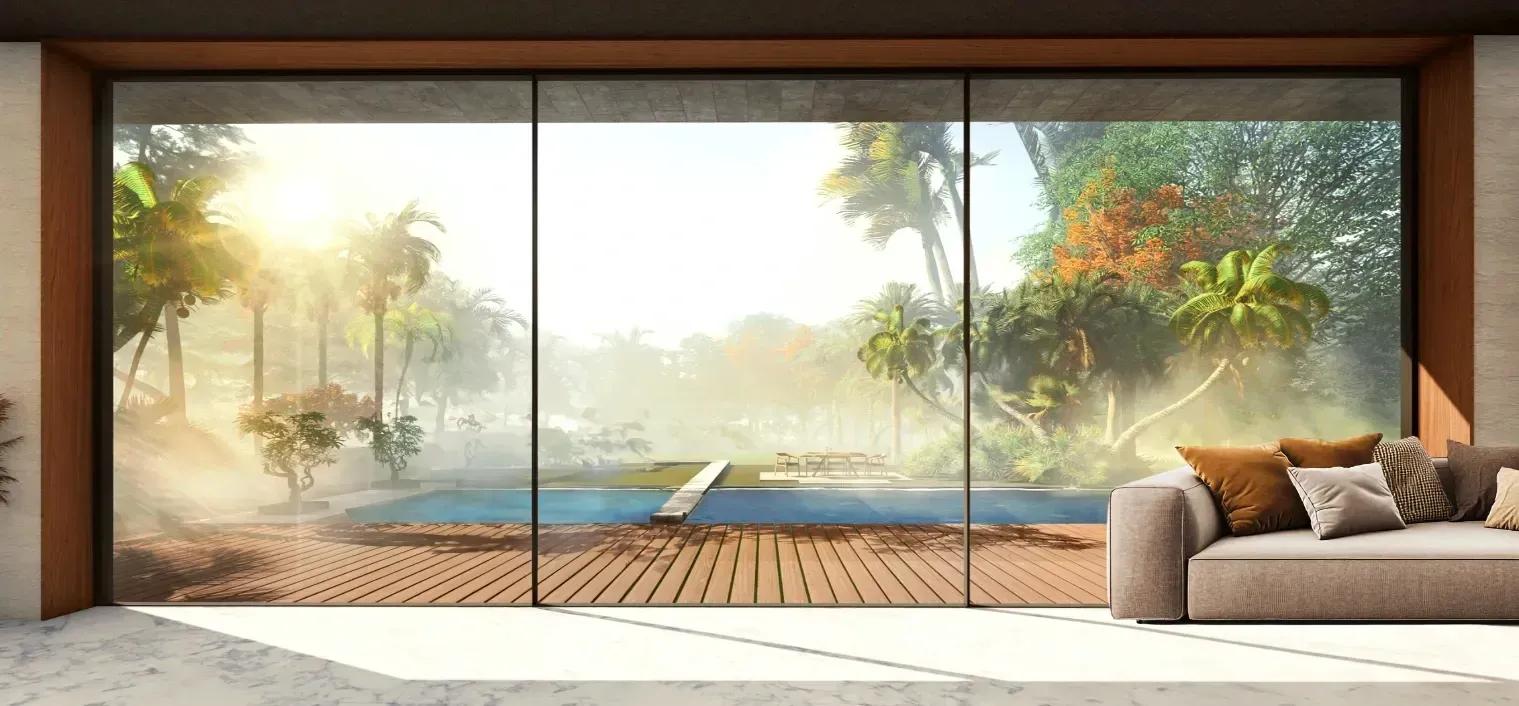

With the advent of Global Warming, energy efficiency and conservation have become paramount factors when designing a building. A typical building contributes to 40 per cent of the total power consumption today. As an interface between indoors and outdoors, the façade plays a significant role in the definition of a building’s energy efficiency. By employing a rear ventilated facade, an energy concept can be developed for each building that takes into account the heating and cooling requirements of the building along with the perfect light quality inside it.
What Exactly is a Rear Ventilated Façade?
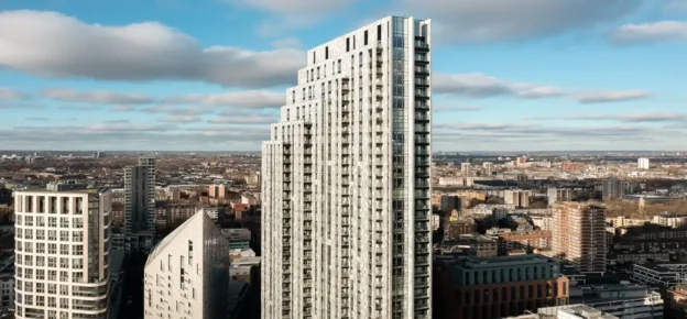
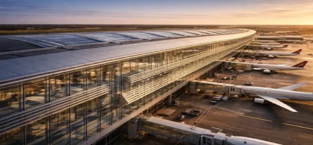
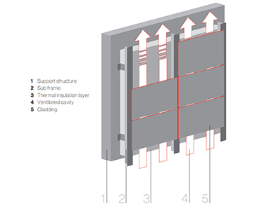
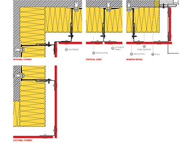
The rear ventilated façade is a multi-layer building façade system consisting of a rainscreen cladding on the outer layer in combination with a frame, weather-resistant membrane, insulation, sub frame and a ventilated cavity. (Image 1)
A differential between the temperature on the face system of the cladding panel and the air cavity temperature creates a variation in air density, resulting in a “chimney effect” that produces upward airflow within the cavity.
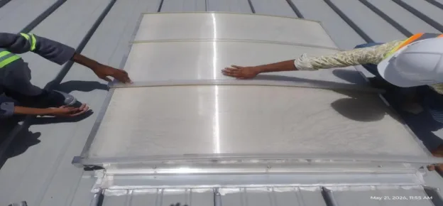
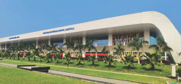
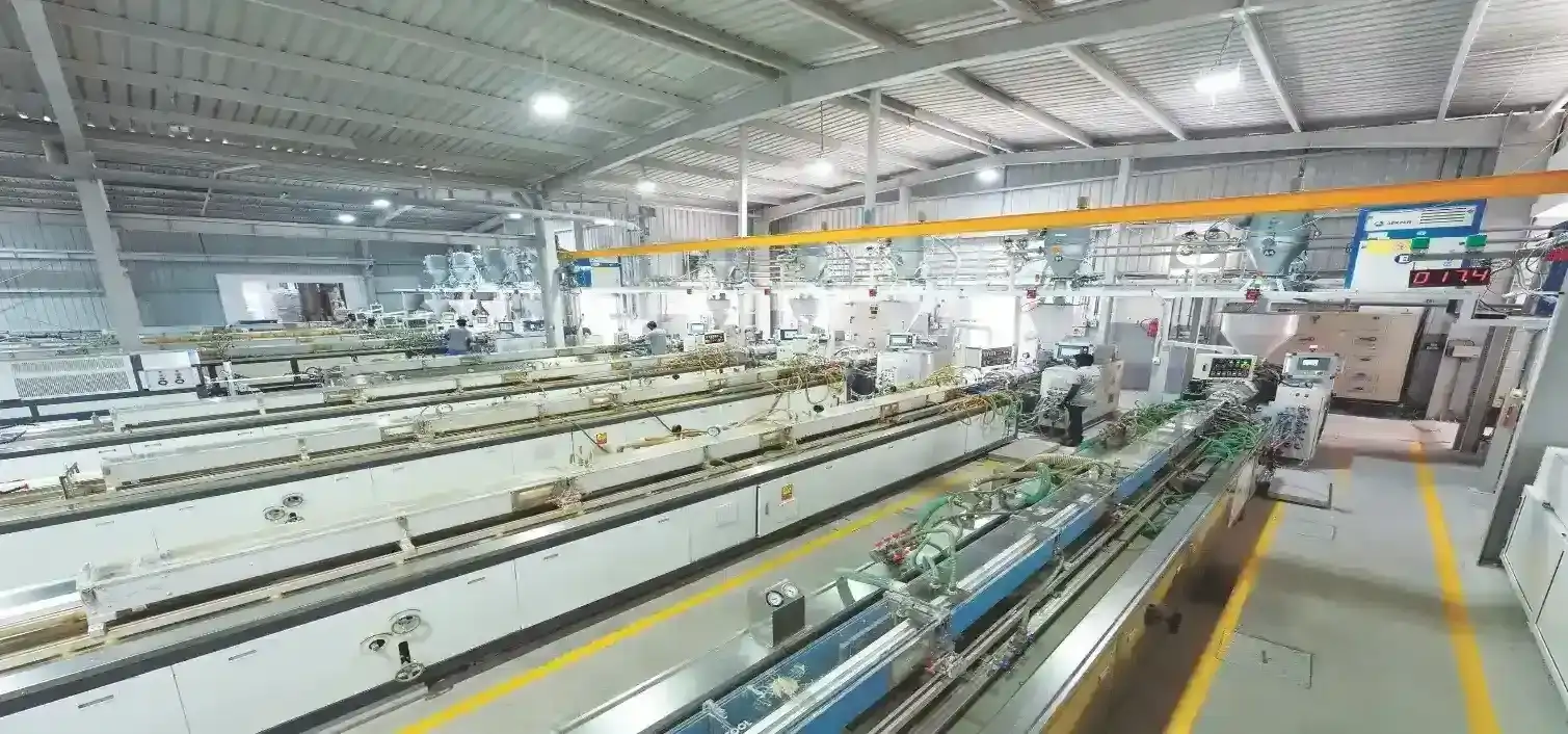
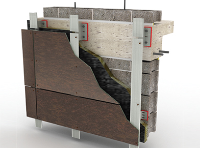
Materials which can be used for rear ventilated façades include HPL and fibre-reinforced resin composite panels, fibre cement, rock wool, ceramics, fine stoneware, copper, titanium zinc, aluminium composite panels, aluminium boards, bricks, façade-quality fabrics and support panel systems system for applications with plaster, glass, hewn stone or ceramics. (Image 2)
How Can a Rear Ventilated Façade Help in Reducing the Energy Consumption of a Building?
Rear ventilated façades with their inherent airflow provide a number of distinct advantages over other façade systems such as:
• Thermal Insulation and Energy Savings -The rear ventilated façade system can be designed for various energy requirements, with individually measured insulation materials of any desired thickness. Thermal bridging is reduced because there are no interruptions caused by floor slabs. Options do exist to help reduce the amount of thermal bridging introduced or even eliminate the thermal bridging altogether by truly insulating continually across all structural members with not breaks or bridges in the insulation except for the finite fasteners used to attach the cladding to the building.
Due to the structure of the rear-ventilated façade, the vapour diffusion resistance decreases from the internal to the external walls. Any moisture from condensation, or accumulated during construction, is channelled through the ventilated space and contributes to a healthy and comfortable indoor climate. The insulation also ensures the highest possible heat retention values for the structure, while it compensates high temperatures in the summer from within, thus resulting in reduction in the heating/ cooling requirements in the interior of the building.
• Acoustic Insulation – Rear ventilated façades positively affect the sound insulating properties of the external wall. Depending on the thickness of the insulation, the dimensions of the cladding and the percentage of open joints, the sound reduction index can be increased by up to 14 dB.
• Environmental Protection – Rear-ventilated façades are resistant to driving rain. Moisture is quickly removed through the ventilated space between insulating material and cladding. The rain protection of the rear ventilated façade works on two levels: The ventilation gap functions as a pressure compensation room, which ensures that, in a worst-case scenario, driving rain is drained over the back of the cladding, thus protecting the thermal insulation from wetness. Hence, it is possible to construct rear ventilated façades with open, horizontal seams without decreasing the protection against rain.
What Energy Parameters Need to be Considered Before Designing a Rear Ventilated Façade?
For overall façade design, the following general parameters should be considered:
- Architectural requirements/restrictions
- Thermal performance to be achieved (U-value, g-value, layer temperatures)
- Flexibility (adjustable performance)
- Interaction strategy with HVAC systems (extract rate, natural ventilation)
Apart from these parameters of a more general nature, the following more specific parameters may prove to have a significant impact on possible design and, therefore, thermal façade performance:
- Loads
- Maintenance (interior or exterior)
- Element module size
- Investment vs. running costs (integrated view)
In the following, however, we will focus on one of the main thermal performance parameters: the U-value from a façade contractor’s point of view.
What is U-value and How is the U-value Calculated?
U-value or Thermal Transmittance is the heat flow density going through one squire metre of a specific wall element when both sides of the wall are subject to a temperature difference of one degree K. U-value gives a measure of the heat loss in any building element such as a wall, floor or roof. It can also be referred to as an ‘overall heat transfer coefficient and measures how well parts of a building transfer heat. U-value measures heat loss by all three heat transfer modes: conduction, convection, and radiation.
U-values are important because they form the basis of any energy or carbon reduction standard. In practice, nearly every external building element has to comply with thermal standards that are expressed as a maximum U-value. The lower the U-value is, the better the element of a building as a heat insulator.
Knowledge of how to calculate U-values at an early stage in the design process helps avoid expensive re-working later on in a project. It allows the designer to test the feasibility of their project at an early stage to ensure whether it is fit for purpose and will comply with regulatory frameworks.
To calculate U-value we first need to find out the thermal resistances of each element (R-values). The R-value is the thickness of the product in meters / Lambda (thermal conductivity). The R-values of all materials used in the application are added and the reciprocal of the resulting sum will give us the U-value for that particular application in the building.
There are different techniques for establishing U-values of walls with rain screen cladding. They are explained below:
a) Detailed Calculations for the Entire Wall: The U-value of the whole wall, inclusive of all fixing arrangements, is assessed by numerical calculation conforming to BS EN ISO 10211. The result applies only to that particular wall as calculated, any variations need to be re-assessed.
b) Using a Linear Thermal Transmittance for a Fixing Rail that Penetrates an Insulation Layer: facade 2-D numerical calculation is undertaken on a section through the wall containing the fixing rail. The boundaries of the model should be at adiabatic positions, for example, mid-way between two rails. The result is compared with a calculation in which the rail is omitted, so as to obtain a linear thermal transmittance, Ψ, as described in BS EN ISO 10211. That calculation needs to be done only once for a given design of rail and penetrated insulation thickness. The U-value of the wall is then U = U0 + (L Ψ / A) where U0 is the U-value of the wall without the fixing rails, L is the total length of rail and A is the total area of the wall.
c) Using a Point Thermal Transmittance for a Discrete Fixing Bracket that Penetrates an Insulation Layer: A 3-D numerical calculation is undertaken on a section through the wall containing a representative fixing bracket. The boundaries of the model should be at quasi-adiabatic positions, for example midway between two brackets. The result is compared with a calculation in which the brackets are omitted, so as to obtain a point thermal transmittance, χ, as described in BS EN ISO 10211. That calculation needs to be done only once for a given design of bracket and penetrated 20 WFM YEAR-END SPECIAL 2015 insulation thickness. The U-value of the wall is then U = U0 + n χ where U0 is the U-value of the wall without the fixing rails and n is the number of brackets per square meter of wall.
With a high thermal performance envelope comes the associated responsibility to account for overheating, air quality and ventilation. Such walls will set the complete building on a path towards very low operational energy and sustainability as long as designers, constructors and owners put the remaining pieces in place and provide the holistic thinking to complete the job.
No allowance in U-value calculations should be made for the effect of the rainscreen cladding itself because the space behind is fully ventilated. The effect of brackets or rails fixing the cladding to the wall behind needs to be allowed for, if the brackets or rails penetrate an insulation layer or part of an insulation layer. As the effect of fixing brackets or rails on the U-value of the wall can be large, even when a thermal break pad is included, their contribution to the overall U-value needs to be assessed by a detailed calculation.
The calculation model should omit the cladding but include the fixing rails or brackets to their full length. The external surface resistance should be taken as 0.13 m²K/W to allow for the shading effect of the cladding.
The air in well-ventilated airspaces is taken as the same as that of the external air. Accordingly, the resistance of the airspace and that of all layers between it and the external environment are disregarded. However, as the cladding provides protection from wind, the external surface resistance is greater than its normal value of
0.04 m²K/W.
What are the Parameters that Can Modify the U-value of a Wall?
The U-value is calculated under standardized conditions, usually under an air temperature of 20 degrees C inside and 10 degrees C outside, a surface emissivity of 0.9, 50 per cent humidity and an external wind speed of 4m/s. However, the U-value is not always constant and can change under the following conditions:
• Change in the External Temperature: Very small influence on the U-value. It does not affect opaque, well-insulated walls. For glazed walls the variation is also very small: a curtain wall with a mean U-value of 1.75W/m2 degree K at +10 degrees C outside will have the same value at -10 degrees C outside, and will raise to 1.76W/m2 degree K when the outer temperature is +30 degrees C.
• Change in the Emissivity of Materials can have an influence, and it varies depending on the material. When a material has an intrinsic low emissivity it is difficult to make a difference on the U-value if we reduce it even further.
• Wind Speed has an important influence if the wall is a glazed façade, and it doesn’t affect the mean U-value if it is a well-insulated opaque wall.
Conclusion:
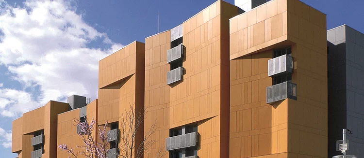
Today, rear ventilated façades are amongst the most popular façade systems. In addition to their functional safety, architects chiefly value the design possibilities provided by the use of rear ventilated façades. These systems are thus less susceptible to damage than other façade systems. In addition, fire, noise and lightning protection requirements can be implemented easily and creatively.
Separating thermal insulation and weather protection materials, the design of a façade with rear ventilation is not only structurally advantageous but also allows the use of different cladding to create a range of effects. A wide range of materials, formats, shapes, seams, colours and mounting types are available to turn custom design ideas into reality.
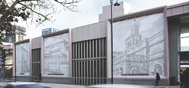
Countless new build and retrofit examples demonstrate how designs incorporating rear ventilated façades address their environments with sensitivity and reflect the character of buildings in the urban space.