
The façade is one of the key elements of buildings across the World. Various types can be found in various countries and regions, often fitting to specific climatic conditions at the location of the building. Among various types, one can identify also ventilated facades (VF), particularly favourable in climates where water vapor transmission through a façade and prevention of condensation in the internal façade structure is of concern.
A ventilated façade (VF) system contains an airgap layer between the inner and outer membranes of the façade system. The air in the gap flows up due to buoyancy and exits the gap from the upper part while cold air enters the gap from the lower part, providing optimal thermal efficiency and moisture removal from the façade structure. In the case of fire, the presence of the air cavity in VF systems influences the overall fire dynamics of the façade. It provides the fire a pathway to spread through the inner part of the system without being noticeable.
The design of VFs can be very complex. Each type of VF is unique in its design to some extent, and therefore the fire protection mechanisms need to be tailored to fit each scenario. It is important to consider strategies that can be useful to avoid this adverse effect, for instance, the implementation of open-state fire barriers.
Fire barriers for Ventilated Facades
The open-state fire barriers (cavity barriers), allow the passage of air during normal operating conditions. The barrier itself is always made of non-combustible materials, often of fire-resistant stone mineral wool.
In the event of fire, the fire cavity barriers are closed, to create a blockage and prevent the spread of hot gases. This blocking can be done mechanically but is more often done using intumescent coatings, which expand to block any air gaps. Intumescent coating’s expansion can only sustain its weight over a small distance, thus open state cavity barriers cannot be installed in VF with large gap widths.
The choice of materials, as well as the dimensions of the air cavity, can largely influence the performance of a VF system in the case of fire.
The materials used in the insulation layer for the inner wall of the ventilated façade, as well as the cladding material for the external walls, can be either combustible or non-combustible in nature. The choice of material influences the fire performance of the entire façade system.
The effect of using combustible materials in the outer wall mainly promotes fire spread over the external wall of the system and increases the overall flammability of the system. Moreover, the external fire spread can lead to the ignition of the inner part of the façade, if combustible materials were used in the insulation layer of the inner wall. When combustible materials are used in the inner wall (insulation layer), the main effect is again the increase of the flammability of the system. The fire behavior in the inner part can be greatly influenced by the presence of the air cavity, and thus the effects of the material of the VF system are of great importance.
However, the fire performance of the façade is not only dependent on the materials present, but also on the air cavity, configuration, and geometry of the façade. A complete assessment of the fire performance of a façade system requires the system to be tested in a large-scale test as it is intended to be used in its end state.
Importance of optimal installation
Being fixed to a combustible element could cause cavity barriers and fire to spread over the façade.
Cavity barriers need to be well fixed into the structure of the inner wall to guarantee functionality. Fixing elements should withstand the actions of the fire and not lose their strength under high thermal exposure.
Several factors can influence the success of such a product. Careful testing of all parameters on several scales is required to be fully confident in the final product’s success. Some of these parameters will be driven by codes and standards, but some can be completely independent of such codes.
As well as ensuring the required performance of fire barriers, manufacturers that want to design new products for any country, need to understand the market and the restrictions imposed by codes and regulations for each country.
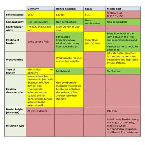
The following table provides an overview and overlap of the main parameters requested by Germany, the UK, Spain, and the Middle East. A colour coding has been implemented to show similarities and differences. Requirements that match completely among countries are shaded with green, requirements that partially match among countries are shaded with yellow, and requirements that completely differ are shaded with purple.
Currently, there is no harmonised European standard for the testing of open-state cavity barriers. The Association for Specialist Fire Protection has published a technical guide (TGD19) which is currently being used by industry. A new European method for testing open-state fire barriers is currently under development.
Case study
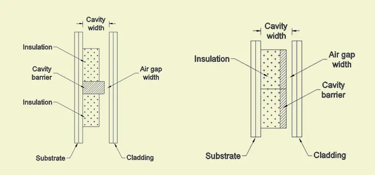
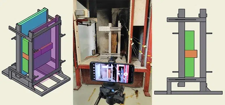
To analyse the identified parameters influencing the implementation of open-state cavity barriers in ventilated façades with non-combustible insulation (rock mineral wool (RMW) and glass mineral wool (GMW)), an experimental campaign was proposed consisting of bench scale tests. The general configuration of the tests is shown in Figure 1.
A testing rig was designed to simulate the conditions within a section of a ventilated façade where the barrier is placed horizontally between the inner wall (substrate) and the outer wall (cladding). The barrier is installed following the suggested configuration of TGD 19 interrupting the layer of mineral wool insulation and under manufacturer’s guidelines.
To have a controlled environment where the testing campaign can be carried out under repeatable conditions, an SBI room was utilised. Figure 2, shows schematics of the rig with a mounted sample and a sample before being tested within the SBI room.
The heat source for the experimental campaign consisted of a propane burner with a linear configuration that fit perfectly in the middle space of the testing rig’s base. The test aimed to produce flames that were in contact with the sample’s cavity barrier to induce a high thermal load over the element. Moreover, a “flashover” like effect was sought where the flames are coming out from the window of a compartment fire and entering the cavity width of a ventilated façade.
The cavity width, air gap, and barrier height were determined according to the available product. (Cavity width: 160 mm, air gap width: 25/30 mm, barrier’s height: 75 mm)
Based on the identified trends regarding the fire resistance requirements per country in Table 1, the testing time for the samples was defined as 30 minutes in this experimental campaign. While fire resistance was not being assessed, it was considered important to capture the thermal field developed over the sample during this time of exposure to analyse the identified parameters over a sensible time.
Sample configuration and recording of data.
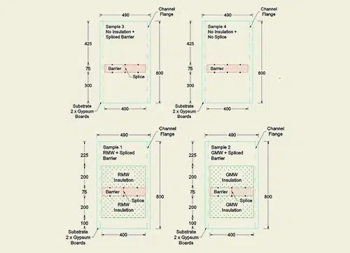
In total, 4 different samples were composed and tested in the following order:
- Sample 3, No Insulation with Splice
- Sample 2, Glass Mineral Wool (GMW) with splice
- Sample 1, Rock Mineral Wool (RMW) with splice
- Sample 4, No Insulation, without Splice.
The chosen configuration of the samples was defined based on exposing the elements with their weakest point in a realistic setup. Thus, the first three samples were assembled with a splice in the middle which was protected with a fire stopping as per manufacturer’s recommendation. Moreover, the fourth sample did not count with any splice in order to compare the behaviour of the elements with and without a splice.
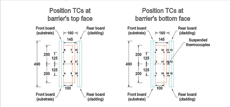
To capture the thermal field development over the samples, thermocouples (TC) type K were placed at the bottom and top faces of the barrier at different locations along the cavity barrier’s length. Thermocouples were also placed in the air gap to determine the temperature change after the closure of the gap by the intumescent. The configuration of thermocouples is shown in Figure 4 below.
Results – Captured thermal field over elements
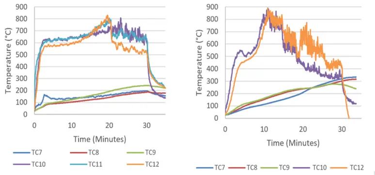
Temperature measurements were registered at the top and bottom face levels of the fire barriers for the four samples. The measurements over the barrier were registered at four longitudinal locations: substrate joint (TCs 1,2,3,4,5,6), mid-body (TCs 7,8,9,10,11,12), air gap (19,20,21), and cladding joint (TCs 13,14,15,16,17,18). As expected, higher temperatures were recorded in the bottom face TCs of the barriers due to direct exposure to fire conditions. Top face barrier measurements of temperature increment were registered to be reduced at the joints (substrate and cladding after intumescent closure). However, different behaviours over the barrier were identified, and the RMW and GMW samples were the most interesting.
Figure 5 shows the TC measurements at the bottom and top face of the barrier for samples 1
(RMW) and 2 (GMW). The readings are at the mid-body location, it can be seen that the generated fire conditions in both sample tests induced a high heat transfer across the body of the barrier, although more severe in sample 2. The temperatures at the top face for this sample reached about 300 °C after 30 min of exposure which implies a high conductive heat transfer across the barrier promoted by the fire conditions of the test. This could imply a breach in the insulation performance of the element and need to be further investigated.
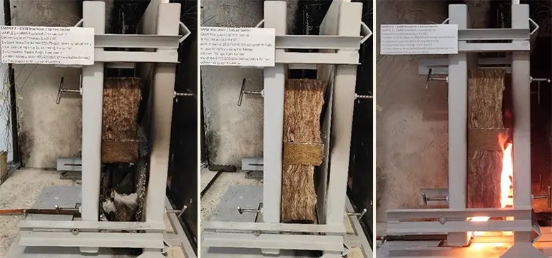
Figure 6 below, shows the evolution of the sample 2 test which resulted in the higher thermal exposure for the barrier due to the melting and collapse of the GMW and the fire conditions this event generated. A similar behavior was observed for sample 1. However, the thermal exposure was lower since the RMW block stayed intact.
DISCUSSION Effect of Insulation
The presence of insulation expedited the performance of the intumescent material compared to scenarios without insulation.
When comparing the two types of non-combustible insulation (Rock Mineral Wool, RMW; and Glass Mineral Wool, GMW), RMW offers a better performance. Fire resistance of RMW to fire-induced alterations ensures minimal changes in fire behaviour. Approximately 20 minutes after ignition, the lower RMW insulation collapsed due to weakened plastic fixations.
Remarkably, post-test images revealed that the RMW remained structurally intact, displaying minor soot accumulation on exposed surfaces. Contrastingly, Glass Mineral Wool (GMW) exhibited inward bending from the middle, generating eddy vortex behaviour within the flames. Ultimately, this generated different exposure conditions and higher heat transfer across the body of the barrier compared to the RMW insulation
Effect of Splice
The presence of splices and fire stoppers used as indicated by the manufacturer does not influence the behaviour of the functionality of the cavity barrier. This is an important matter as in construction, splices are used and should perform just as well as if the system did not have splices or joints in the cavity width. This also helps to mimic a more realistic setting for the open- state cavity barriers.
Plastic Fixation
The insulation fixations are made of polypropylene and presented a melting behaviour during the experiments of Samples 1 (RMW) and 2 (GMW). Even with the collapse of the insulations, the cavity barrier still performed well and did its job of not allowing the passage of flames and hot gases. In a real scenario of a ventilated façade, the fall of the insulation must be investigated, as it can change the behaviour of the fire by falling and resting in a different position than the original one and even investigate the toxicity associated with the melting of the fixation.
Performance of Intumescent
The time of closure is deemed as the time of complete closure along the barrier’s length. Observations suggest that the intumescent reacts faster when the flames are closer to it. However, the intumescent reacts unevenly closing the locations with higher temperatures first. Nevertheless, this does not affect its ability to close the gap effectively and within a reasonable timeframe. In the case study, all the intumescent reacted in such a way that they completely closed the air gap, producing between 27 mm and 35 mm of horizontal expansion.
General Conclusion
The experimental campaign presented here investigated the variables of insulation type and the use of splices within cavity barriers. The results presented provide some insight into the behavior of these variables, as well as establish some further variables and parameters that are recommended for investigation. The heat transfer mechanism, fixation material, effects of geometry, and the effect of the rain screen should be investigated in further work.
In the tests completed, rock mineral wool performed better when compared to glass mineral wool. Glass mineral wool is more likely to deform and collapse, potentially leading to issues around conduction across the cavity barrier. The extent of this conduction needs to be further investigated since it could compromise the performance of the element. The splice seems to have no significant effect on the performance of the cavity barrier if it is installed correctly.
The investigation was very limited, as no repetitions were made due to time constraints, and the system was only tested for a maximum of 30 minutes. The rig was also bench-scale and did not follow a standardized heating curve. It only aimed to replicate a direct exposure of the elements to flames. This may provide a lack of comparison to the full-scale installation of the fire barrier
Related Post