
They have become the façade of choice across the globe; however, lightweight aluminium curtain walling systems can present specifiers with a host of internal sound transmission issues that need to be addressed to ensure the well-being, happiness and productivity of building occupants. Mike Carrick AMIOA, Head of Acoustics at Siderise Group, looks at the common sound transmission paths in lightweight curtain-walled buildings and the performance-limiting factors when considering the flanking sound transmission performance both vertically and horizontally.
With the extensive use of specialist criteria, complex jargon and the many ways of referring to the humble ‘decibel’ – Rw, Dnf,w, DnT,w, Dnc,w – to name but a few, the world of acoustics can be confusing to those who are not involved in the subject. This can lead to misunderstandings or worse, the misapplication of materials needed to achieve good acoustic standards or to solve sound transmission issues.
When considering ‘floor to floor’ sound performance, overall performance is effectively controlled by the ‘weakest link’. This means that very careful consideration should be given to potential weak points to ensure that they do not become the ‘limiting factors’ in overall sound transmission performance. The curtain wall, together with movement joints, should be considered as potential weak points and thoroughly assessed accordingly.
A Route to Compliance
Whatever the building type, whether it be an office, hotel, school or apartment building, the client requires a sustainable building that is fully robust and compliant with all building regulations and design criteria.
When considering the vertical transmission of airborne sound energy (floor-to-floor), the applicable criteria (regulatory or otherwise) will usually be in dB in one of the following forms:
DnT,w – a Final Site Measured Value
A DnT,w is a final site measured value and will be controlled by both the ‘Rw’ value of the floor slab (direct sound transmission) and the Dnf,w value of the façade (flanking sound transmission).
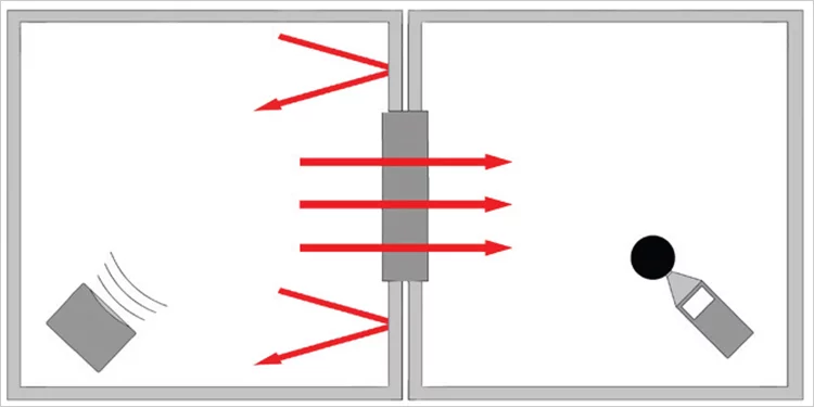
Rw – a Laboratory-Tested Value for a Component
An Rw value is a laboratory test value for a component or construction, such as a concrete floor slab, partition, window, door, etc.
The laboratory comprises of two fully isolated chambers, defined as the source room and receiving room, with an aperture between these 2 rooms. The sample material or construction is fitted into the aperture, and the test is carried out.
The acoustic performance between these chambers is very high, at least 10dB at all frequencies higher than the test specimen and therefore any sound energy that passes from one chamber to the other is considered to have travelled through the test specimen (Direct Sound Transmission).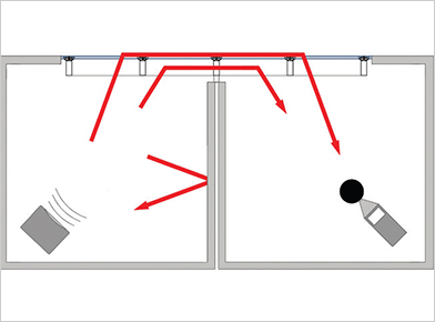
Dnf,w – A Laboratory Tested Value For A System
A Dnf,w value is a laboratory test value for a system, such as a curtain wall system, raised access floor or suspended ceiling system.
As with the laboratory configuration for the aperture testing, it comprises two fully isolated chambers, but the apertures are adjacent to each other, rather than opposing. The sample construction is fitted across both apertures, and the test is carried out.
The acoustic performance between these chambers is very high, at least 10dB at all frequencies higher than the test specimen and therefore any sound energy that passes from one chamber to the other is considered to have travelled through the test specimen (Direct Sound Transmission).
It is essential to understand the important and significant differences between these in order to validate or otherwise prove potential compliance. In general, site-measured values cannot match those recorded in a sound laboratory. The difference will vary depending on the method of test and actual performance levels, but as a guideline, a 5-10dB minimum practical difference is commonly quoted.
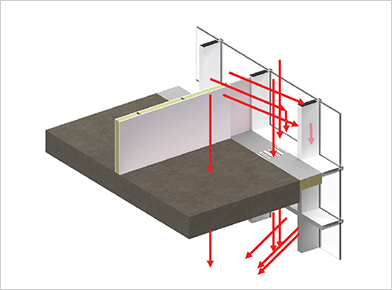
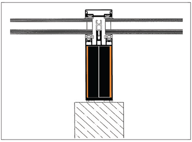
The 5 Common Flanking Paths for a Standard ‘Stick Curtain Walling System’
The Dnf w value is the total flanking sound transmission of the façade system. It does, however, comprise a number of individual sound transmission paths with the 5 main path elements being: a) the glazing element, b) the transoms, c) the structural element of the mullion, d) the hollow of the mullion and e) the movement zone.
A number of factors directly affect the overall performance, including the span between the mullions and transom, the stiffness, number of façade brackets, type of glass, glass orientation, twin or single mullion or transom designs and importantly, the use of façade acoustic enhancement products.
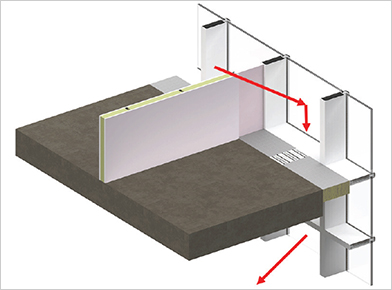
A) The Glazing Element
This transmission path occurs when sound energy in the source room hits the glass and becomes structure-borne by inducing vibrations in the glass. These vibrations travel into the gasket of the transom, into the transom itself, and then back into the spandrel panel via the second gasket. They then travel into the next transom (based on a twin transom design) and into the glass area, which is remote from the original source, finally re-radiating into the adjacent room.
Positive Factors
- Twin Transom design
- Split Transom
- High Performance Glass
Negative Factors
- Single Transom Design
- Un-split Transom
- Low Performance Glass
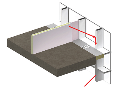
B) Transoms
This transmission path occurs when sound energy in the source room hits the transom, travels through the frame into the spandrel zone, and past the floor slab. It then travels through the next transom (based on a twin transom design) into the adjacent room above or below. Single transom designs are generally significantly lower performing than twin transom designs. Use of high mass materials between the transoms, which can be incorporated into the fire seal specification, or use of specialist acoustic inserts inside the transoms, can be particularly effective in reducing sound transmission via this path.
Positive Factors
- Twin Transom design
- High mass treatments
- High Performance
- Fire Seal
Negative Factors
- Single Transom Design
- Lightweight Hollow Aluminium
- Poor Performing Fire
- Seals
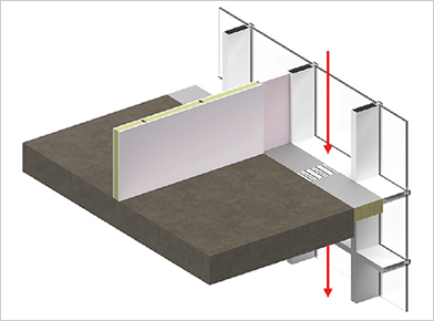
C) The Structural Element of the Mullion
This transmission path occurs when sound energy in the source room hits the mullion and becomes structure-borne by inducing vibrations in the aluminium. These vibrations travel easily up or down the façade and then re-radiate into the adjacent rooms. Test data suggests that this causes the most issues in the 500Hz – 1000Hz range of frequencies, which is also where the human ear is most sensitive. Continuous mullions past the floor slab are one of the main potential ‘Performance Limiting Factors’ in façade design. The splitting and then re-joining of mullions with a joining spigot at the floor line shows a large increase in potential overall performance, while fully decoupled mullions/framing at the floor line show further improvement.
Positive Factors
- Decoupled Framing
- Split Mullions
- Damping Materials
Negative Factors
- Fully Connected Framing
- Continuous Mullions
D) The Hollow of the Mullion
This transmission path occurs when sound energy in the source room hits the mullion, passes through into the hollow of the mullion, a highly reverberate area, then travels up or down the building and breaking back out again into adjacent rooms above or below. Use of specialist acoustic baffles, either thin baffles based on high mass materials or purely absorption with a greater depth can be particularly effective in reducing sound transmission via this path.
Positive Factors
- Baffles in the Mullion at Floor Line
Negative Factors
- Hollow Section
- Continuous
E) The Movement Zone
The movement cavity is a potential weak point when considering floor-to-floor performance and is often not included when façade testing is carried out in laboratories. Quite rightly, system manufacturers are there to test their system and not a proprietary fire stop, but when designing buildings, these cavities are included, and therefore it is important to recognise the potential for this to reduce the overall Dnf,w performance of the façade.
Commonly, interior linings, such as plasterboard ceilings, steel plates, floor screeds, raised access floor systems, are present and provide the additional mass required, but where ‘acoustic holes’ are present, such as roller blinds, air ventilation systems, recessed lights, lightweight suspended ceilings, lightweight aluminium closure plates etc, then the acoustic properties of the fire seal and acoustic upgrades are important.
Overall Performance
 The overall performance is a combination of all these path elements and can only be established by full façade testing in an accredited laboratory, which can be time-consuming and very expensive. It is possible for a project noise consultant to look at specific project details at the slab edge, compare the design with known library data and assess the possible overall performance. However, this would not necessarily offer any guarantee of compliance.
When assessing any design, it is important to understand that the overall performance would be wholly controlled by the weakest path element, referred to as the ‘Performance Limiting Factor’ and therefore any design change or acoustic enhancement should only be considered if all other path elements are capable of meeting the same value or being upgraded to meet the value.
 For example, if a continuous mullion (Path ‘C’ above) is only able to achieve a maximum of 48dB Dnf,w then there is little point in improving the performance of ‘Path B’ to 55dB as, overall, it would still only be 48dB due to ‘Path C’ being the ‘Performance Limiting Factor’. Therefore, unless an improvement can be made additionally to Path B, for example, by splitting the mullion, there would be no benefit in upgrading any other path elements to above 48dB.
Performance criteria for commercial developments generally range between 40dB Dnf,w to 53dB Dnf,w, whereas residential developments range between 55dB Dnf,w to 65dB Dnf,w. Sometimes, however, for various reasons, values outside these ranges may be required. As such, it is essential to establish the precise project requirements and determine if +Ctr is applicable. This can usually be found in the project acoustic report.
Library Data (Vertical Sound Transmission)
Test data from various system manufacturers can help in understanding likely performance-limiting factors.
The values given below are based on library data and are for guidance. However, project-specific details should always be assessed individually and designs approved by the project noise consultant based on actual laboratory data or assessment by an acoustic engineer.
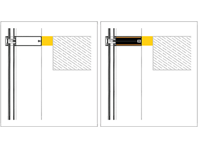
Single transom, continuous mullion values range from 35dB Dnf,w (untreated) to 46dB Dnf,w (with acoustic enhancements). This type of detail is generally not ideal for residential developments, but may be acceptable for commercial developments.
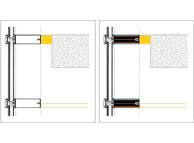
Twin transom, continuous mullion values range from 42dB Dnf,w (untreated) to 46dB Dnf,w (with acoustic enhancements). Overall performance is being limited by the continuous mullion. This type of detail is generally not ideal for residential developments, but may be acceptable for commercial developments.
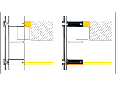
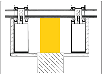
Twin transom, split mullion re-joined with a joining spigot, values range from 50dB Dnf,w (untreated) to 55dB Dnf,w (with acoustic enhancements). Overall performance has increased due to the million being split. This type of enhanced detail is likely to be acceptable for residential developments, and may be acceptable for commercial developments without enhancement.
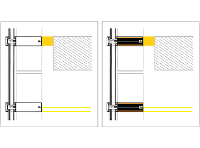
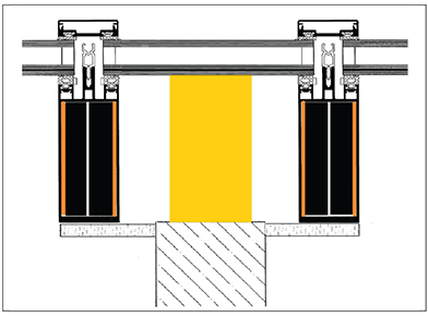
Twin transom, split mullion, fully decoupled frame, values range from 50dB Dnf,w (untreated) to 65dB Dnf,w (with acoustic enhancements). Overall performance has increased significantly due to the fully decoupled frame. This type of detail enhancement is likely to be acceptable for almost all residential developments.
Library Data (Horizontal Sound Transmission)
The values below are for guidance only.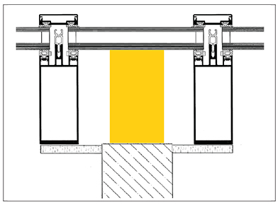
Twin Mullion configuration, partially boxed in, fully boxed in, partially boxed in with acoustic mullion inserts, values range from 50dB Dnf,w (untreated) to 65dB Dnf,w (with acoustic enhancements). This type of detail enhancement is likely acceptable for almost all residential developments.
Single Mullion configuration, untreated/empty, treated/acoustically enhanced, values range from 44dB Dnf,w (untreated) to 53dB Dnf,w (with acoustic enhancements). This type of enhanced detail is possibly acceptable for residential developments, but if empty, it is unlikely to be acceptable for commercial or residential.
Façade Product Enhancements
SIDERISE, manufacturers of acoustic and fire insulation products for over 40 years, offers a large range of tried and tested product enhancements specifically developed for the façade industry. The product range, designed to reduce vertical and horizontal sound transmission in curtain wall buildings, includes a choice of effective and proven sound reduction solutions that deal with all common sound path problems and are frequently used to assist in reducing flanking transmission between adjacent internal areas.
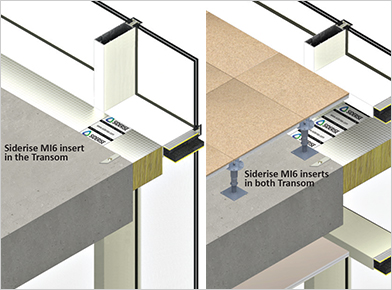
Single Transom Designs
Use of the Siderise MI6 mullion/transom inserts in a single transom design can increase the potential performance from circa 35dB Dnf,w to the maximum possible, 46-50dB Dnf,w depending on the precise detail.
Twin Transom Designs
Siderise MI6 mullion/transom inserts in a twin transom design can increase the potential performance when high mass floors and ceiling abut the transoms, without the need to enhance the slab edge fire seal.
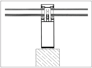
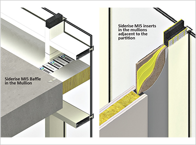
Millions (Central to the Room)
Site test data suggests the use of the Siderise MI5 foam baffle in mullions central to the room can increase the site measured values by a potential of 2-4dB overall.
 Single Mullions (Abutting Partitions)
The installation of the Siderise MI6 mullion/transom inserts in a single mullion design can increase the potential performance from circa 44dB Dnf,w to the maximum possible, 51-53dB Dnf,w depending on the precise detail. The detailed product between the partition and the mullion is the Siderise FIP panel, with a performance of 46dB Rw and up to 1 hour rating.
Perimeter Barrier Fire Seal
There are many fire seal products
available, claiming compliance with common fire standards. However, other equally important characteristics and properties of the seal should be considered when selecting the product: sound transmission performance, ability to expand and contract with the facade’s cyclic movement, a proven fire performance (both integrity and insulation) when abutting deforming structures, provision of an effective smoke seal, resistance to moisture/water and ability to provide a flexible closure limiting possible flanking transmission.
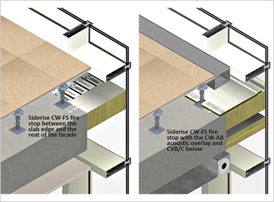
Perimeter Barrier Fire Seal (Acoustic Enhancements)
In addition to the fully tested acoustic properties of the Side-rise CW-FS system, the Side-rise CWAB acoustic overlay and Side-rise CVB/C10 lower barrier are fully tested with exceptionally high performances suitable for almost any criteria.
In a world where we are experiencing increasing noise levels, occupant complaints and dissatisfied clients, acoustics in the built environment has become a concern to society and a challenge to designers. It is all too common when considering the specification of the seal between the slab edge and the facade, for product selection to be based exclusively in terms of compliance with the relevant fire regulations. For façade engineers, architects and their clients, it is essential that due consideration is given to both the acoustic implications and performance of the closure arrangement, ensuring any potential weak point in curtain-walled buildings is controlled. The use of performance-enhancing products will mitigate against these issues.
For further information about SIDERISE or for technical advice, visit www.siderise.com or call +44 (0)1656 730833.