Designing and implementing fire safety into buildings can be a complicated task as it requires architects, design & fire consultants, contractors & material suppliers to be aligned in several ways. Fire codes provide the minimum requirements based on learning from past incidents and observation.
These requirements provide the framework & boundaries to architects & consultants designing buildings. The codes also help: material suppliers to produce standard materials, contractors to objectively price and plan for construction work, and authorities and regulators to objectively look at buildings to evaluate how fire safety will be implemented for buildings which are competing to differentiate themselves from other buildings.
One such code is the UAE Fire and Life Safety Code of Practice whose 2018 revision, takes a slightly different approach as compared to highly prescriptive codes often used around the world. The code uses several international standards to avoid alienating materials from prominent supply chains.
The code also references (test) standards without their year of publication and mandates the latest revisions to be used. Both these steps create unique challenges in construction projects as architects; design & fire consultants, contractors & material suppliers are not used to such an approach.
The code now includes a chapter on the responsibilities of stakeholders to not only address this unique approach but also to handle the growing need to bring out responsibility / liability in the construction industry and to offer a clear path for performance-based approach to fire safety.
While façade fire safety continues to be a topic of debate across the world, one of the key tools to quantify the effectiveness of fire safe designs is the NFPA 285 test method which is a ‘Standard Fire Test Method for Evaluation of Fire Propagation Characteristics of Exterior Wall Assemblies Containing Combustible Components’. Earlier this year, the 2019 version was released updating the standard after 7 years.
As the UAE code could be the earliest adopters of the new test method, the article aims to bring about better understanding of the differences between the superseded 2012 version and the 2019 version to help users of this test method make better decisions to help them avoid potential liabilities in the future.
Use Of The NFPA 285 Test Method In The UAE FLS Code
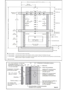
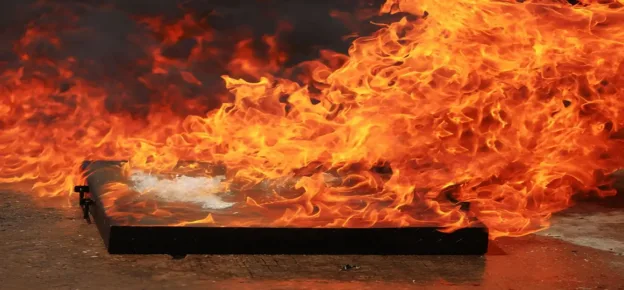
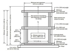
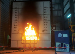
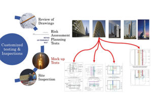
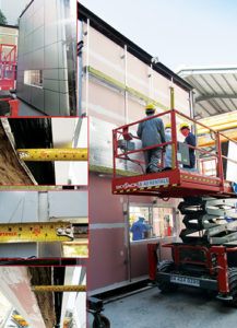
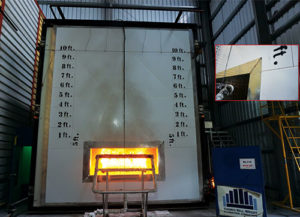
The test method documents the resultant fire propagation response of specific cladding details (a combination of materials brought together in a unique design) under laboratory conditions by installing a mock-up of the cladding detail in a very specifically designed mock-up rig. Figures 1, 2, 3 and 4 showing mock-up rig dimensions, a test in progress, an example of installation in progress, and details of thermo-couples (temperature sensing devices) respectively.
The UAE Code Uses this Test Method in Two Ways:
• Setting minimum compliance requirements for use of specific materials to be used as key façade elements. This is done using a combination of tests validating their individual reaction to fire properties and using the NFPA 285 test to bring about evidence of the successful use of a material in the mock-up one possible detail of a cladding system.
The NFPA 285 test also helps material manufacturers provide a proven system design to façade engineers who want to avoid designing new systems for their projects.
• To create evidence of the behavior of one or more potential high-risk cladding buildups for a specific project. Such evidence is used by fire consultants / façade engineers to confidently take on the risk / liability detailed in the code. Unlike the testing laboratories or manufacturers who may not have a full picture of all possible fire risks in the cladding of a building and understand occupancy related fire safety and its related risk mitigation plan.
These are known well to fire consultants / façade engineers who need to understand, interpret and use the results of such tests effectively. Figure 5 shows a typical approach for quality assurance and how a given cladding could have several details which may need to be validated using one or more NFPA 285 tests.
What Has Changed?
There are Three Key Changes:
Bearing and non-load bearing: By removing the word non-load-bearing from the title and various clauses of the test standard the new version has been revised to include both bearing and nonload- bearing assemblies.
The test does not evaluate the load-bearing or non-load bearing characteristic of the mock-up built on the G+1 test rig. The cladding system does not support a building element other than itself, like a floor slab, being self-supporting and is different than other non-load bearing elements like partitions.
The test method only documents the resultant behavior of the potential fire propagation of an installed mock-up under laboratory conditions. Horizontal and vertical panel joints: While evaluating a cladding assembly under NFPA 285, both horizontal and vertical joints, their specific locations with respect to the window opening (hence, their proximity to direct flame impingement from the window burner); provided a good understanding of the resultant system behavior.
The 2012 edition, allowed subjective decisions to be taken by the user of the report to establish limitations. As an example, when tested with joints with a given proximity to the window burner; indicating a worst-case scenario allowed the interpreter of the test to draw a very broad ‘Field of Application’.

The 2019 edition now requires a continuous, vertical panel joint within 1 foot of the vertical centre line of the window head and an additional horizontal panel joint between 1 and 3 feet of the window head. This reduces the degree of subjective decisions of the limitations between tested and installed configurations. These could previously be stated or established at the discretion or interpretation of the user of the test report. Figure 6 to see an example of joints.
Field of Application means use of technical justifications to state that an alternative design/ configuration/ material combination will pass the same test without have to conduct it again. This is done by establishing that the system that has been tested is the worst possible scenario from a fire risk standpoint and alternative scenarios which would be less risky and would hence pass a test.
There are exceptions to this rule. Firstly, there are systems using continuous materials like Exterior Insulation Finishing Systems (EIFS) and plaster based systems which do not incorporate joints of any type. Additionally, there are sites or application specific tests which do not have an intention to extrapolate the results to factor in the variation of joints.
Window Head Detailing: The window head is the most impinged upon area of the specimen by the heat radiated from the room and window burners and is the most vulnerable point of the mock-up.
Specifically for isolation from scenarios that may lead up to the chimney effect and resultant cavity flaming causing the failure of the mock-up/ design. The requirement of the window opening in a test mock-up is often difficult for users to relate to many system designers as the building may not have a window opening.
The test method aims to address several potential fire risk scenarios by creating and exposing such an opening.
In a typical cladding system, there is a gap between the panels / cladding fascia of the system and the substrate on which it is applied. This gap is an opening into the air cavity behind the panels which, if breached, allows flame impingement on both sides of a system, instead of from only the exterior.
The older editions of the standard did not give guidance on the use of methods to isolate the air cavity (like galvanized steel, insulation materials, etc.). This cavity would thus become protected and the potential risks in the design do not get fully evaluated, shown in Figure 7 NFPA.
The 2019 edition of the standard sets a requirement to close the air gap at the head of a window with a single sheet of 1mm thick aluminium, with zero overlaps on the exterior face, limited fixing points, and no extra insulation near the window head. This not only provides a limited amount of protection, and a more onerous condition, but also homogenises test configurations. This helps mitigating ambiguities in a ‘Field of Application’ and reduces opportunities for manipulation.
Co Author : Brett Shinn
Fire Engineer,
Thomas Bell- Wright International Consultants