
A façade typically represents 30 per cent of the total development cost. The taller and more complex the building becomes, the figures escalate. A key component of the cost is the thickness of glass, framing members and size of brackets – all of which are largely dictated by the wind loads that the building is subjected to. I
In today’s world, tall buildings dominate the skyline, thus defining the prosperity of any modern city. Over the last two decades, the number of tall buildings over 200m in height has increased by 352 per cent (Reference CTBHU Research) and is growing. An estimate shows that Asia alone accounts
for more than 70 per cent of high buildings, which are above +200 m, globally.
With the early involvement of façade engineering expertise, savings can be made through the coordination of the structural design. Added value can be achieved with a façade design that is sympathetic to the local environment, meets the performance parameters and maximises a development’s overall value.
Advanced engineering methods should be considered when optimising the façade design for wind loads. These include wind tunnel testing and Computational Fluid Dynamics (CFD). The application and benefits of these methods are discussed in the context of two case studies: Port Baku Towers 2 in Azerbaijan and Mitre Square in London.
The Challenge
Wind pressure assessment is a key parameter when designing the façade. The accurate prediction of wind pressure becomes more critical while dealing with complex and high-rise structures. It not only helps to mitigate wind-induced damages, such as broken glass and failure of the façade structure or components, but also directly correlates to the initial high capital cost of the façade.
Accurate prediction of wind pressures is essential at an early stage of development to ensure the feasibility of a façade design in terms of safety and economics. While dealing with complex and tall buildings, it is always recommended to use a scaled wind tunnel test, as results have shown that the wind loads calculated based on codes can be too conservative compared to wind tunnel tests and potentially lead to higher façade costs.
In the case of tall and complex buildings, CFD wind simulations should be considered in the earlier stages to assess the risk associated with the desired architectural intent. It provides façade engineers with sufficient information to calculate the façade system structure based on localised pressures rather than the overall pressure.
The movements and deformations that need to be considered while designing the façade include differential column shortening, lateral story drift, building racking, slab and beam edge deflections and building vibrations.
Strong collaboration between the façade engineer and the structural engineer becomes a priority to ensure the façade performs as intended. A lack of coordination can have a significant impact; failure modes may include panel fallout, connection failure, excessive rotation of glass within the framing, and irregular joints.
To accommodate high inter-story drift due to high wind and seismic loads, customisation of the façade system may be required in some cases, with wider vertical joints and stiffer profiles. These considerations are explored further in the case studies that follow.
Case Study 1
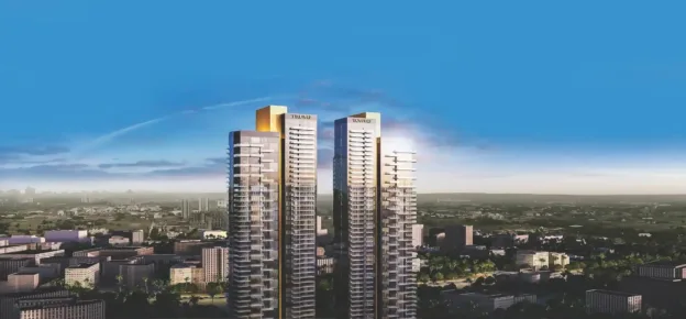
Port Baku Tower 2
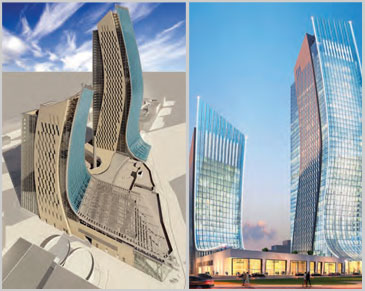
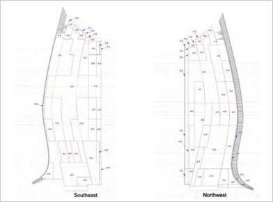
The original development comprised 2 towers (240m and 100m), a 4-storey podium with shopping facilities and a multi-storey underground car park. The complex façade geometry mainly comprises a curved unitised curtain wall along the south face, resulting in a spectacular skylight over the main entrance area. In all, there were 12 different façade typologies that were defined and designed accordingly.
Considering the complex geometry, there were initial challenges involved in determining the wind loads for the façade elements. This was resolved by conducting wind tunnel testing on a scaled model of the development. Pressures were determined for each façade elevation. The results were quite challenging as wind pressures were shown to be in excess of 4.0 kPa at podium levels and up to -7.5 kPa for the main tower areas.
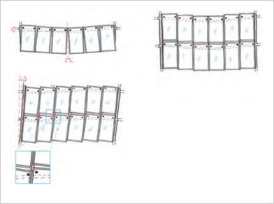
These high-magnitude wind pressures resulted in the bespoke design of fa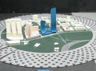 çade system elements. A unitised façade system was developed to overcome problems associated with the installation of a stick system and reduce on-site installation time.
Coordination at an early stage with the structural consultant resulted in an agreement on the allowable building movements, deflection and structural tolerances. Slab edge deflections for the structure were limited to 1.5mm/1m length for the dead load to reduce any potential racking façade panel units. The vertical and horizontal joint widths of the units, as well as restraints, were designed to accommodate all the building movements and prevent any potential rotation of panels.
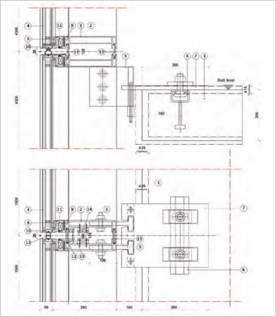
The designed joints between the units were also assessed, taking into consideration the worst-case scenario to accommodate the movement resulting from the inter-storey drift, considering the limit of H/300 to the peak high magnitude wind load/ Seismic loads.
Challenges also involved designing unique façade brackets due to the complex geometry and high wind loads. The special bracket was designed to safely transfer the loads back to the main structure without compromising the structural integrity of the façade system.
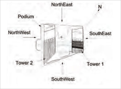
Peak Net & Differential Facades/Cladding Negative Pressures
Notes:
- All values presented are in kPa
- All pressures stated are working pressures and need to be applied in conjunction with the appropriate code-compliant wind-loading combination factors.
- For architectural features of the proposed development, where both sides of surfaces are exposed to the wind, such as parapets, canopies and roofs, cladding pressure is assessed as peak differential pressures (resulting net wind force. All other areas are assessed as peak net pressures, which incorporate internal pressures
- Geometries presented in red indicate the louvres on the proposed development
- Geometries presented are in Full-scale measurements in units of mm
QUICK FACTS
Project: Port Baku Tower 2
Location: Baku, Azerbaijan
Architect: Chapman Taylor Architects
Façade Types: Curved Unitised Façade, Solid Rainscreen Cladding Louvred Façade, Storefront Façade, Podium Terrace, Standing Seam Roofing System, Skylight
Status: Re-design
Case Study 2
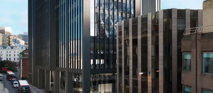
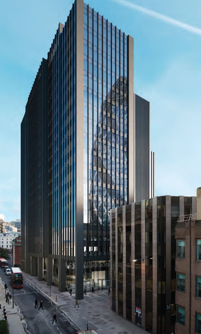
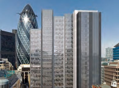
Creechurch Place
Creechurch Place is a 96 m tall office building. The façade mainly comprises a double-skin curtain wall, which incorporates an automated blind system within the cavity and an inner operable leaf for cleaning and maintenance access. There were 15 different façade typologies that have been defined and designed accordingly.
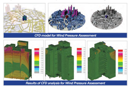
CFD analysis has been used by the façade engineering team to determine initial cladding loads and enable more detailed pressure maps for the established elevations compared to code calculations.
The units have been designed by means of temperature analysis in the ventilated cavity, which comprises air intake through the transom joint and an air outlet staggered through perforated parts in the mullions, creating hidden vents. This design allowed for a reduction in external pressures by ventilation (pressure equalised system) and significantly reduced potential water ingress.
Even though every unit has been fitted with an operable full-height window, the air leakage could be reduced to a very low ratio, way below the usual requirements. This could be achieved using standard window components comprising triple gaskets with multi-lock ironmongery in combination with the external laminated glass, which reduces the stress on the inner construction.
Early involvement in specialised high-rise façade engineering can not only significantly reduce the overall façade investment, through identifying the need for and carrying out methods such as wind tunnel testing and/or Computational Fluid Dynamics (CFD), but can also deliver considerable benefits in terms of performance and appearance. Ultimately leading to a conducive environment for its occupants and adding value to the overall scheme.
QUICK FACTS
Project: Creechurch Place
Location: London, UK
Architect: Sheppard Robson Architects
Façade Types: Unitised Façade, double Skin with Vertical Fins, Long Span Double Height Glazing Louvred Façade, Link Bridge, Structurally Bonded Double Glazing
Status: Under Construction